Projection type video display apparatus

a video display and projection technology, applied in the direction of television systems, instruments, color signal processing circuits, etc., can solve the problems of insufficient brightness, short service life insufficient cooling of liquid crystal panels, etc., and achieve low cost, high brightness, and low cost

Inactive Publication Date: 2007-05-22
MAXELL HLDG LTD
View PDF6 Cites 15 Cited by
  • Summary
  • Abstract
  • Description
  • Claims
  • Application Information

AI Technical Summary

Benefits of technology

[0009]The present invention is made by taking the matter mentioned above into consideration, and an object of the present invention is to provide a projection type video display apparatus provided with a light pipe which can cool a liquid crystal panel by a simple structure.
[0011]In particular, in the case that the first and second holes are provided near the incoming side opening portion of the light pipe, a baffle plate is provide in the inner portion of the light pipe for forming a wind path of an intake air and an exhaust air. Accordingly, it is possible to make a cooling effect higher.
[0012]Further, the light pipe is structured by forming a mirror reflecting the light to an inner wall surface of an optical case serving as a structure body holding the illumination optical system irradiating the light from the light source to the liquid crystal panel. Accordingly, it is possible to achieve a low cost.
[0013]In accordance with the present invention, it is possible to make the projection type video display apparatus low cost.

Problems solved by technology

The LED light source has the feature that the color purity is high, and the like, however, has a problem that a brightness is not sufficient as the light source for the projection type video display apparatus in comparison with a high pressure mercury lamp or the like.
In this case, since the temperature of the liquid crystal panel becomes high as mentioned above, there is a tendency that a cooling of the liquid crystal panel is insufficient, and there is a risk that a problem that the service life of the liquid crystal panel is shortened.
In the patent document 1 mentioned above, since the rod lenses are respectively provided in correspondence to the LED constituting an LED light source array, a structure of an illumination optical system conducting the illumination light from the LED to the liquid crystal panel is complicated, and it is hard to achieve a further low cost.

Method used


Image

  • Projection type video display apparatus
  • Projection type video display apparatus
  • Projection type video display apparatus

Examples


embodiment 1

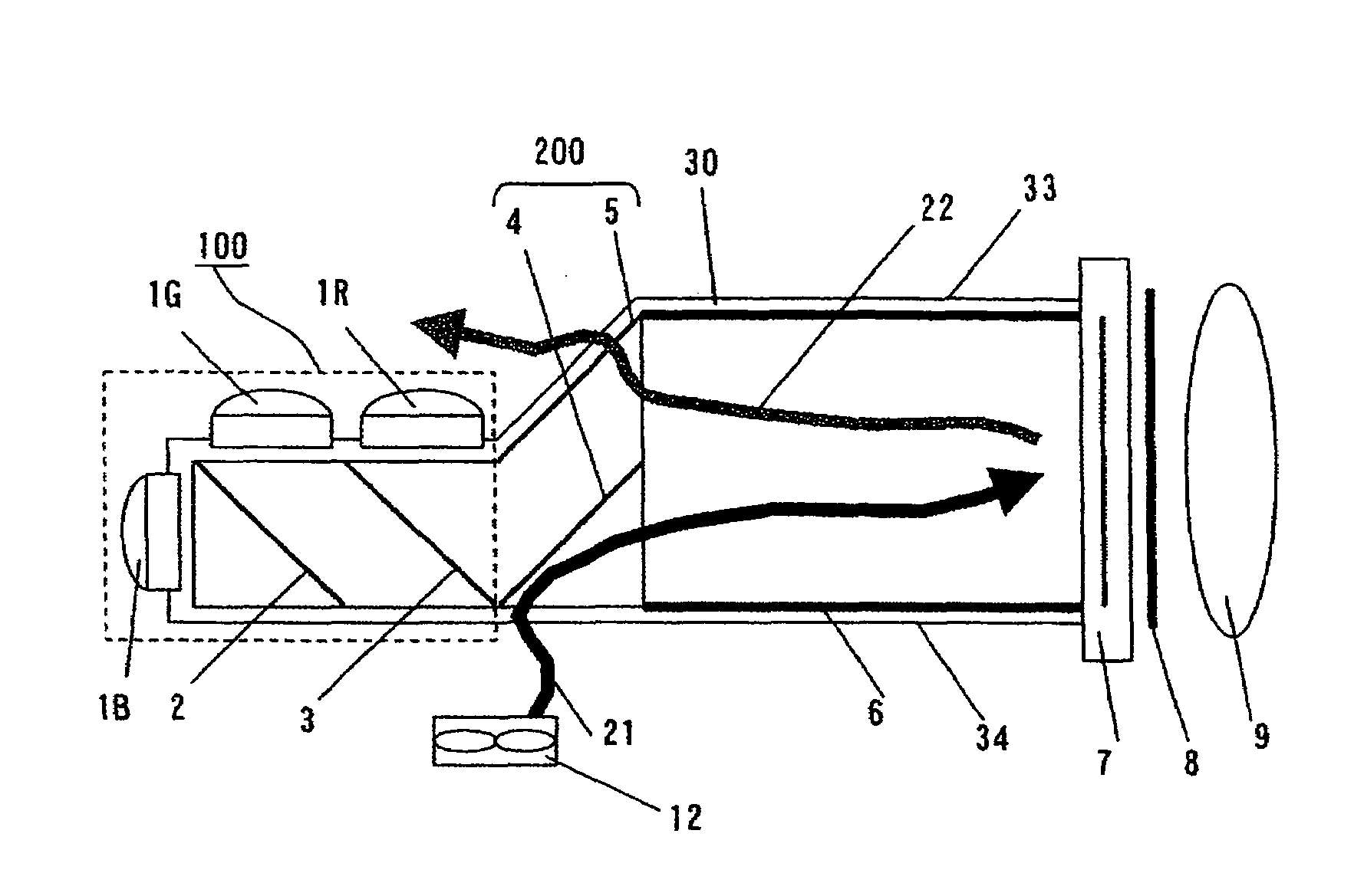
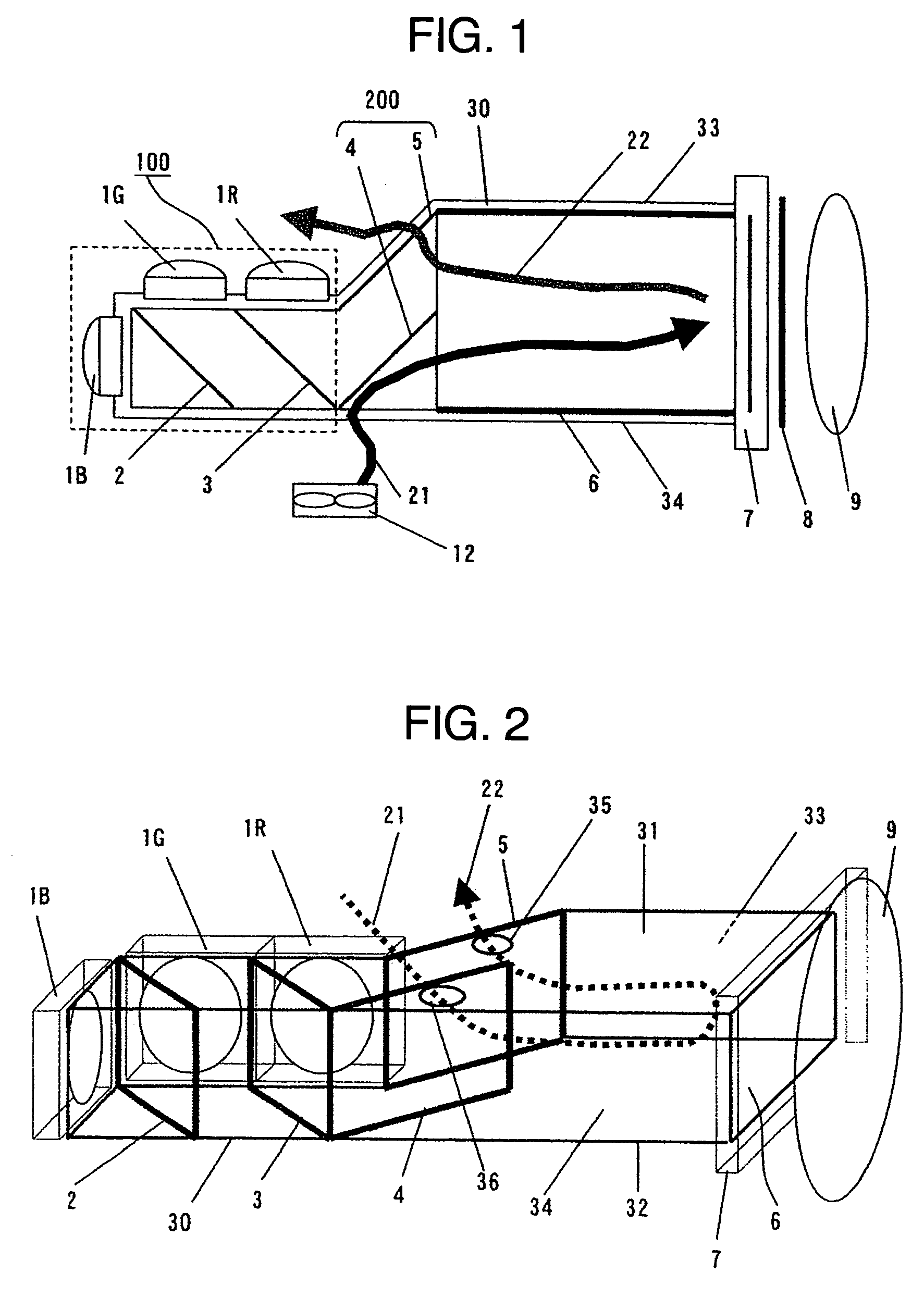
[0023]FIG. 1 is a top elevational view of an outline structure of an optical system of a projection type video display apparatus showing a first embodiment in accordance with the present invention, and FIG. 2 is a perspective view of FIG. 1. In FIGS. 1 and 2, reference symbols 1R, 1G and 1B respectively denote LED light sources emitting a red light, a green light and a blue light, and reference numerals 2 and 3 denote first and second combined mirrors to which a dichroic coat is applied. Reference numeral 4 and 5 denote a polarization separating mirror and a total reflection mirror constituting a polarizing and converting means 200 for aligning a direction of polarization with a predetermined direction of polarization, reference numeral 6 denotes a light pipe serving as a kaleidoscope type integrator in which an inner portion is hollow, reference numeral 7 denotes a transmission type liquid crystal panel, reference numeral 8 denotes an outgoing side polarizing plate, and reference n...

embodiment 2

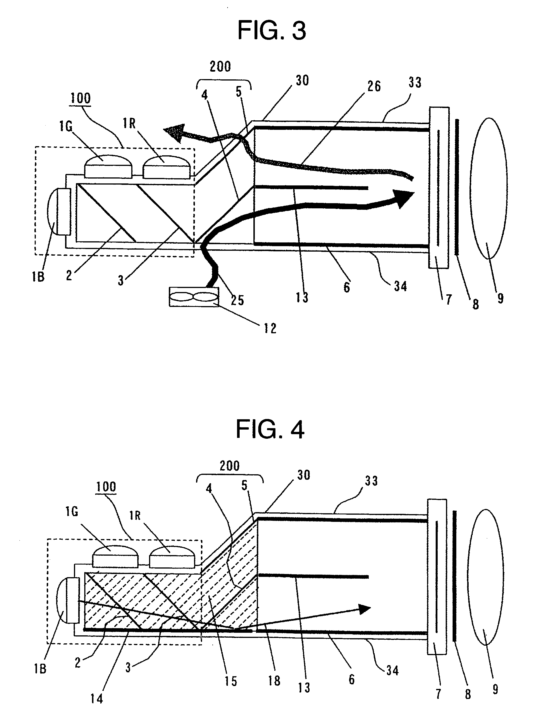
[0033]Next, a description will be given of a second embodiment in accordance with the present invention. FIG. 3 is a top elevational view of an outline structure of an optical system of a projection type video display apparatus showing a second embodiment. In the case that both of the intake hole and the exhaust hole are provided in the incoming side of the light pipe, the cooling wind collide with each other within the light pipe 6. In accordance with the second embodiment, in order to prevent the cooling efficiency from being lowered due to the above collision, as shown in FIG. 3, a baffle plate 13 is provided in the inner portion of the light pipe 6.

[0034]In FIG. 3, the baffle plate 13 forms a wind path of the cooling wind shown by an arrow 25 and an arrow 26 in the inner portion of the light pipe 6, and can efficiently cool the incoming side polarizing plate (not shown) and the liquid crystal panel 7. It is desirable that a length of the baffle plate 13 is at least equal to or m...

embodiment 3

[0041]Next, a description will be given of a third embodiment. FIG. 4 is a top elevational view of an outline structure of an optical system of a projection type video display apparatus showing the third embodiment. In accordance with the third embodiment, when the light pipe 6 is formed by providing with the mirror on the inner wall surface of the optical case, for example, in accordance with the painting or the coating as mentioned above, an area of reflection is simultaneously expanded by providing with the mirror on the inner wall surface of the optical case in the other portion than the light pipe 6.

[0042]In FIG. 4, the inner wall (except the portion of the light pipe 6) of the optical case provided with the mirror for expanding the area of reflection corresponds to the inner wall portion of the upper surface 31 and the lower surface 32 of the optical case 30, and the inner wall portion of the side surface 34 in a side of the holding portion of the polarization separating mirro...


PUM

PropertyMeasurementUnit
lengthaaaaaaaaaa
light permeableaaaaaaaaaa
colorsaaaaaaaaaa

Abstract

An object of the invention is to achieve a high intensity, a compact structure, a cost reduction and a heat radiation of a liquid crystal panel, in a projection type video display apparatus employing a combination of LED light sources and a light pipe. The light pipe is formed in a hollow type so as to be utilized as a cooling wind path. Further, a permeable or reflective baffle plate is provided within the light pipe. Further, the light pipe is formed by coating a mirror on an inner surface of an optical case integrally formed by fixing optical parts. Further, a dichroic mirror is arranged in an LED light source outgoing surface.

Description

INCORPORATION BY REFERENCE[0001]The present application claims priority from Japanese application JP2004-012595 filed on Jan. 21, 2004, the content of which is hereby incorporated by reference into this application.BACKGROUND OF THE INVENTION[0002]The present invention relates to a projection type video display apparatus employing a video display element such as a transmission type liquid crystal, a reflection type liquid crystal, a digital micromirror device (DMD) constituted by a micro mirror or the like.[0003]There has been known a projection type video display apparatus such as a liquid crystal projector or the like which applies a light from a light source to a video display element such as a liquid crystal panel or the like, and enlarges and projects an image on the liquid crystal panel. In recent years, in accordance with a high intensity of a light emitting diode (hereinafter, refer briefly to “LED”), there has been considered to apply the LED as a light source of the projec...

Claims


Application Information

Patent Timeline
Patent Type & Authority Patents(United States)
IPC IPC(8): G03B21/26F21V7/20G02B6/00G02F1/1335G03B21/16G03B21/20G03B21/28H04N5/74F21V29/505G02F1/13G02F1/13357G03B21/00G03B21/14
CPCG03B21/26H04N9/3152H04N9/3164
Inventor YAMASAKI, FUTOSHIYATSU, MASAHIKO
Owner MAXELL HLDG LTD
Why Eureka
Try Eureka