Tunnel magnetoresistance element

a tunnel magnetoresistance and element technology, applied in the field of tunnel magnetoresistance elements, can solve the problems of limited spin polarization, unstable surface, and magnetoresistive effect, and achieve the effects of reducing the roughness of the ferromagnetic layer, reducing the magnetostatic coupling between the ferromagnetic layer and the surface roughness

Inactive Publication Date: 2007-05-22
NAT INST OF ADVANCED IND SCI & TECH +1
View PDF14 Cites 43 Cited by
  • Summary
  • Abstract
  • Description
  • Claims
  • Application Information

AI Technical Summary

Benefits of technology

[0016]In view of the second problem, a second object of the present invention is to develop an element structure in which electron scattering of a nonmagnetic interlayer is prevented and in which magnetoresistive effect is not reduced by the presence of the nonmagnetic interlayer, and to provide a tunnel magnetoresistive element in which the bias voltage dependence of the magnetoresistive effect can be artificially controlled by precisely controlling the thickness of the nonmagnetic interlayer.
[0039][21] A tunnel magnetoresistive element described in [15], wherein a (001)-oriented layer formed by combining Au, Ag, Cu, Al, Pt, Ir, Pd, Mo, W, Ta, Cr, Ru, Rh, Mn, Fe, Co, and Ni is disposed between the underlayer and the magnetoresistive element, and thereby evenness is improved and electrode resistance is reduced.

Problems solved by technology

However, the tunnel magnetoresistive effect, first, has a problem in that it is limited by spin polarization (P1 and P2 in equation (2)) of the electrode material.
However, since such a semimetal is of a compound, its surfaces are unstable.
No material suitable for practical use has been discovered.
Unfortunately, such a new material does not generally provide good magnetic characteristics.
Second, in general, the tunnel magnetoresistive effect is monotonously decreases as bias voltage increases.
This decrease of magnetoresistive effect with increasing bias voltage is not easily controlled because it is an intrinsic problem resulting from increase of magnon scattering or phonon scattering.
Although the bias voltage dependence of the magnetoresistive effect has been successfully controlled to some extent, characteristics sufficient for practical use have not been achieved.
This however makes it difficult to form the element on a silicon LSI, and thus a challenge for realizing a magnetic random access memory has not yet overcome.

Method used


Image

  • Tunnel magnetoresistance element
  • Tunnel magnetoresistance element
  • Tunnel magnetoresistance element

Examples


first embodiment

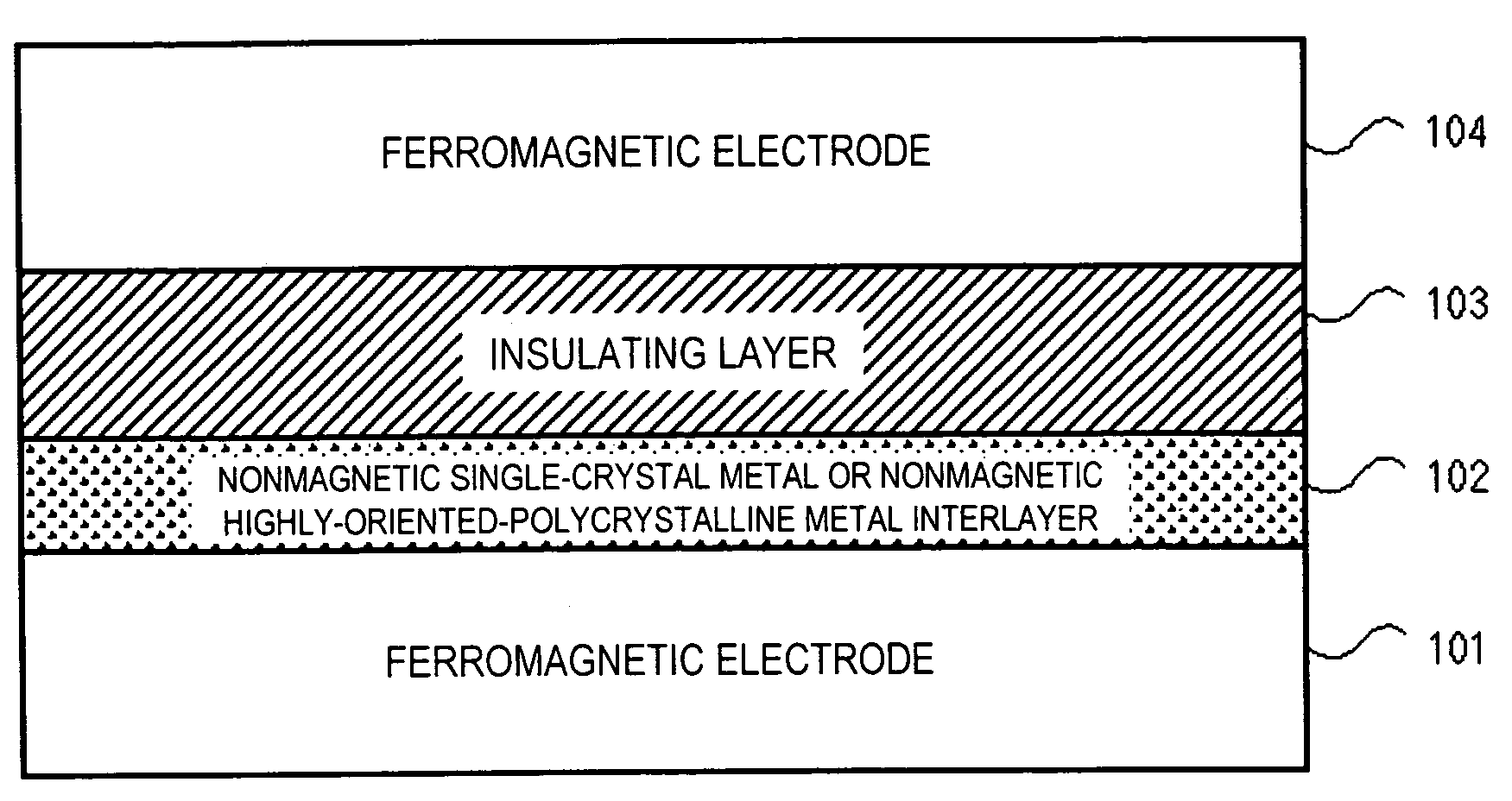
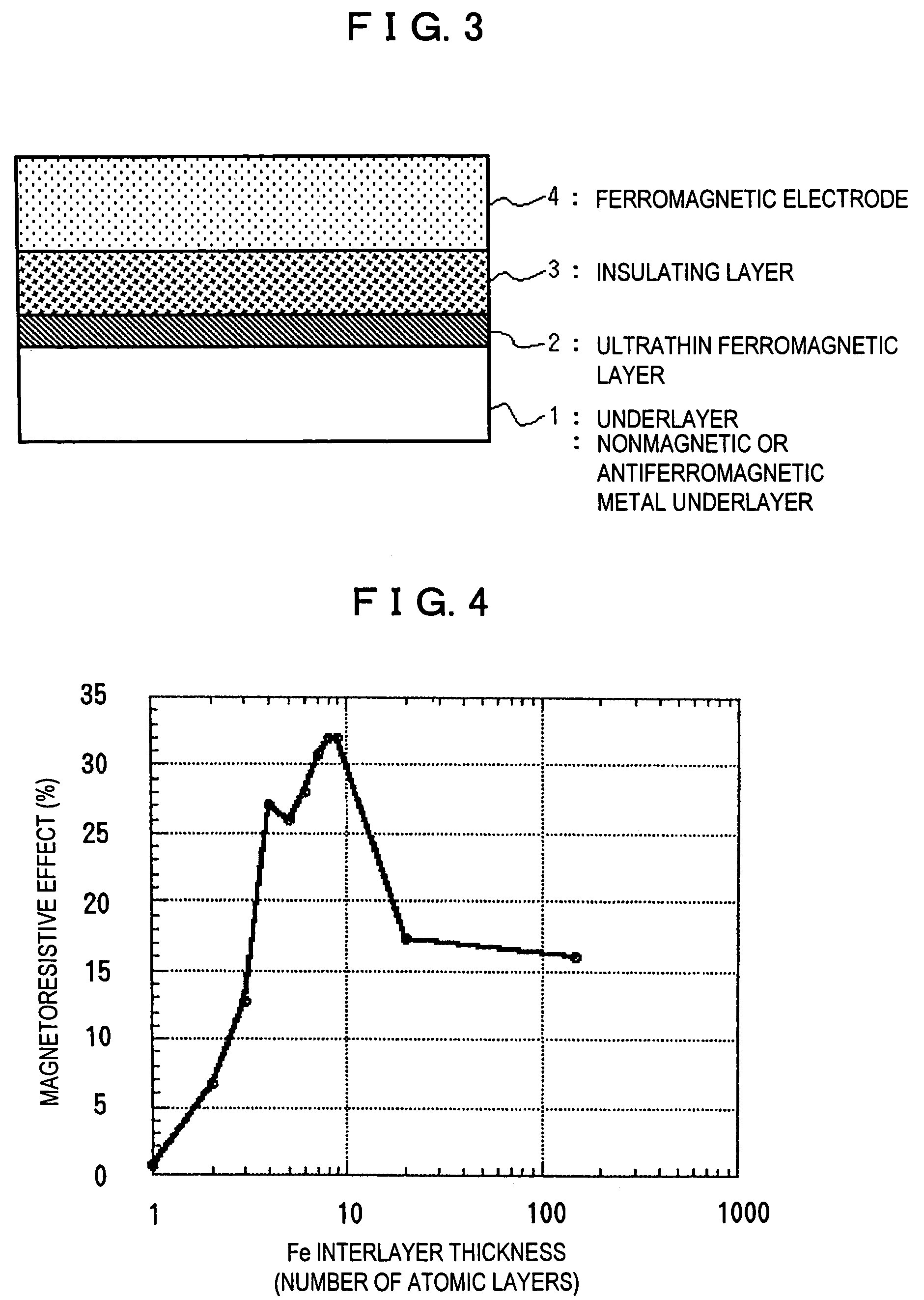
[0059]FIG. 3 is a sectional view of a ferromagnetic tunnel magnetoresistive element according to the first group of the present invention.

[0060]In this figure, reference numeral 1 designates an underlayer formed of, for example, a nonmagnetic metal film or an antiferromagnetic metal film, and reference numeral 2 designates an ultrathin ferromagnetic layer. The thickness of the ultrathin ferromagnetic layer is set in the range of 1 to 15 atomic layers. Reference numeral 3 designates an insulating layer, and reference numeral 4, a ferromagnetic electrode.

[0061]By providing the ultrathin ferromagnetic layer (thickness: 1 to 15 atomic layers) 2 between the underlayer 1 and the insulating layer 3, the spin polarization of the ferromagnetic layer is increased and, resultingly, a large magnetoresistive effect is produced. The spin magnetic moment of Fe atoms isolated in a vacuum is about 4 μB (μB: Bohr magneton) per atom. However, if the Fe atoms enter a crystal to form a body-centered cub...

second embodiment

[0068]FIG. 5 is a sectional view of a ferromagnetic tunnel magnetoresistive element according to the first group of the present invention.

[0069]In the second embodiment, the nonmagnetic or antiferromagnetic metal layer 1 in the first embodiment is replaced with an artificial antiferromagnetic coupling layer 13 including a nonmagnetic or antiferromagnetic interlayer 12 (the composition contains Au, Ag, Cu, Cr, Pt, Pd, Ir, Ru, Rh or an alloy of these metals) formed on a ferromagnetic exchange-coupling layer 11 (the composition contains ferromagnetic metals, such as Fe, Co, Ni, or an alloy of these metals, and other metals, such as Pt, Pd, Ir, and Ru; the thickness is 0.7 to 1.5 times that of the ultrathin ferromagnetic layer 2). Thus, the magnetization of the ultrathin ferromagnetic layer 2 is fixed by the antiferromagnetic exchange coupling with the ferromagnetic exchange-coupling layer 11.

[0070]This structure allows the magnetization of the ultrathin ferromagnetic layer 2 to be fixe...


PUM

PropertyMeasurementUnit
surface roughnessaaaaaaaaaa
thicknessaaaaaaaaaa
thicknessaaaaaaaaaa

Abstract

By varying only the thickness of a known material having superior magnetic characteristics to increase spin polarization without changing the chemical composition, a tunnel magnetoresistive element capable of producing a larger magnetoresistive effect is provided. The tunnel magnetoresistive element includes an underlayer (nonmagnetic or antiferromagnetic metal film); an ultrathin ferromagnetic layer disposed on the underlayer; an insulating layer disposed on the ultrathin ferromagnetic layer; and a ferromagnetic electrode disposed on the insulating layer.

Description

TECHNICAL FIELD[0001]The present invention relates to tunnel magnetoresistive elements, and particularly to a ferromagnetic tunnel magnetoresistive element outputting a large signal, a tunnel magnetoresistive element in which the dependence of the magnetoresistive effect on bias voltage is controlled, and a tunnel magnetoresistive element whose crystal orientation is set to the (001) direction of a body-centered cubic lattice, a face-centered cubic lattice, or a tetragonal lattice.BACKGROUND ART[0002]The tunnel magnetoresistive effect is a phenomenon in which the electrical resistance of a ferromagnetic tunnel junction including an insulating material between two ferromagnetic metal electrodes is varied depending on the relative magnetization directions of the two ferromagnetic electrodes. The magnitude of magnetoresistance is expressed by the following equation:Magnetoresistive effect=[(Antiparallel R−Parallel R) / Parallel R]×100 (%)   (1)[0003]Parallel R represents electrical resis...

Claims


Application Information

Patent Timeline
Patent Type & Authority Patents(United States)
IPC IPC(8): G11B5/39G01R33/06G01R33/09G11C11/16H01F10/32H01L21/8246H01L27/22H01L43/08
CPCB82Y10/00G01R33/06G01R33/093G01R33/098G11B5/3909G11C11/16H01F10/3231H01F10/3254H01L43/08B82Y25/00Y10T428/1143H01L27/222Y10T428/1114Y10T428/1193Y10T428/1157H10B61/00H10N50/10H01L27/105
Inventor NAGAHAMA, TAROYUASA, SHINJISUZUKI, YOSHISHIGE
Owner NAT INST OF ADVANCED IND SCI & TECH
Why Eureka
Try Eureka