Light emitting device
a technology of light-emitting devices and light-emitting tubes, which is applied in the direction of discharge tubes/lamp details, discharge tubes luminescnet screens, gas-filled discharge tubes, etc., can solve the problems of insufficient reliability of bam, short life, and inability to meet the needs of use, and achieves efficient light-emitting and color-purity-efficient effects
- Summary
- Abstract
- Description
- Claims
- Application Information
AI Technical Summary
Benefits of technology
Problems solved by technology
Method used
Image

Examples
first embodiment
[0090
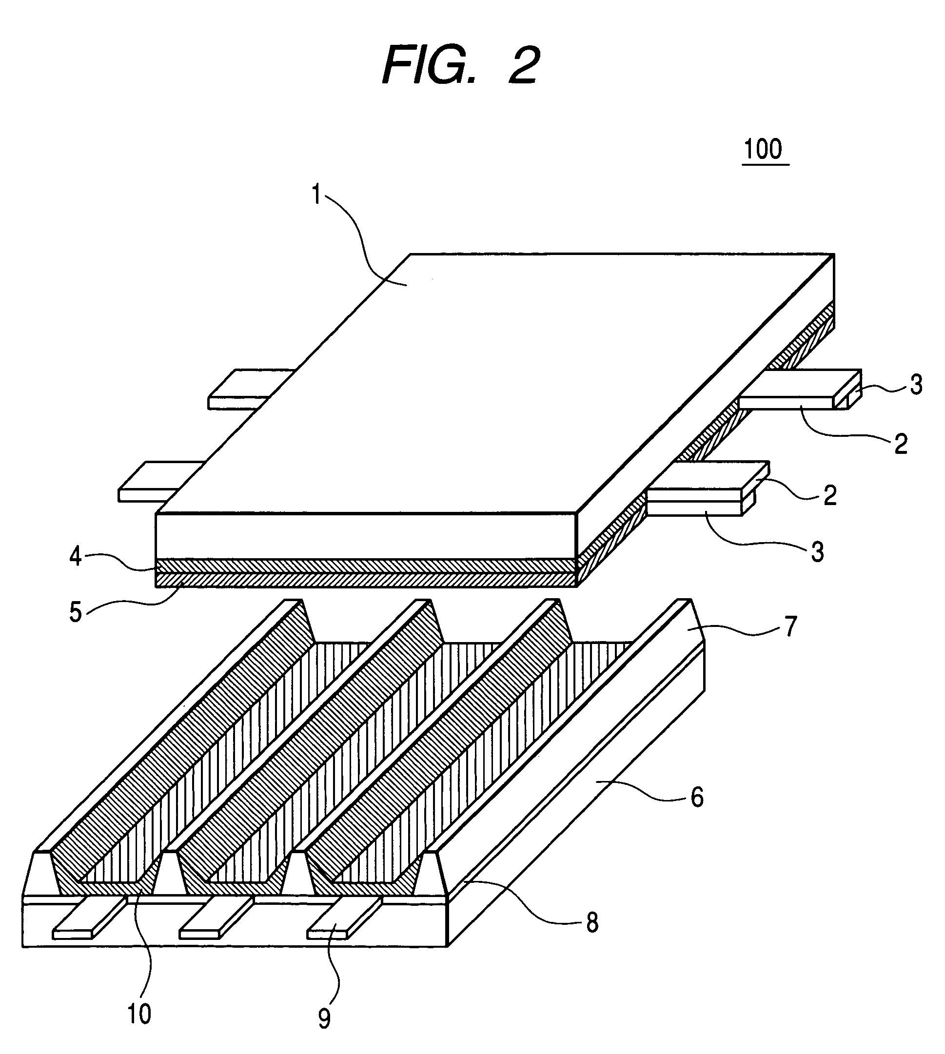
[0091]In the present embodiment, preparation of a phosphor, preparation of a plasma display panel using the phosphor, and preparation of an image display device using the plasma display panel will be sequentially illustrated with reference to the drawings.
[0092](1) Preparation of Phosphor
[0093]A phosphor was synthetically prepared as a constitutional member of a plasma display panel according to the first embodiment of the present invention.
[0094]The resulting phosphor has a composition of Sr2.98MgSi2O8:Eu0.02.
[0095]The phosphor was prepared in the following manner. Initially, 4.399 g (29.80 mmol) of SrCO3, 0.962 g (10.00 mmol) of MgCO3, 1.202 g (20.00 mmol) of SiO2, 0.0352 g (0.10 mmol) of Eu2O3, and 0.392 g (4.00 mmol) of NH4Br as a flux were weighed, were fully mixed in an agate mortar, the resulting mixture was charged into a heat-stable vessel and was heated at 1250° C. in a reducing atmosphere for three hours.
[0096]The heated product was pulverized, was washed with water,...
second embodiment
[0122
[0123]Initially, a material phosphor was synthetically prepared for the preparation of a plasma display panel according to the second embodiment of the present invention.
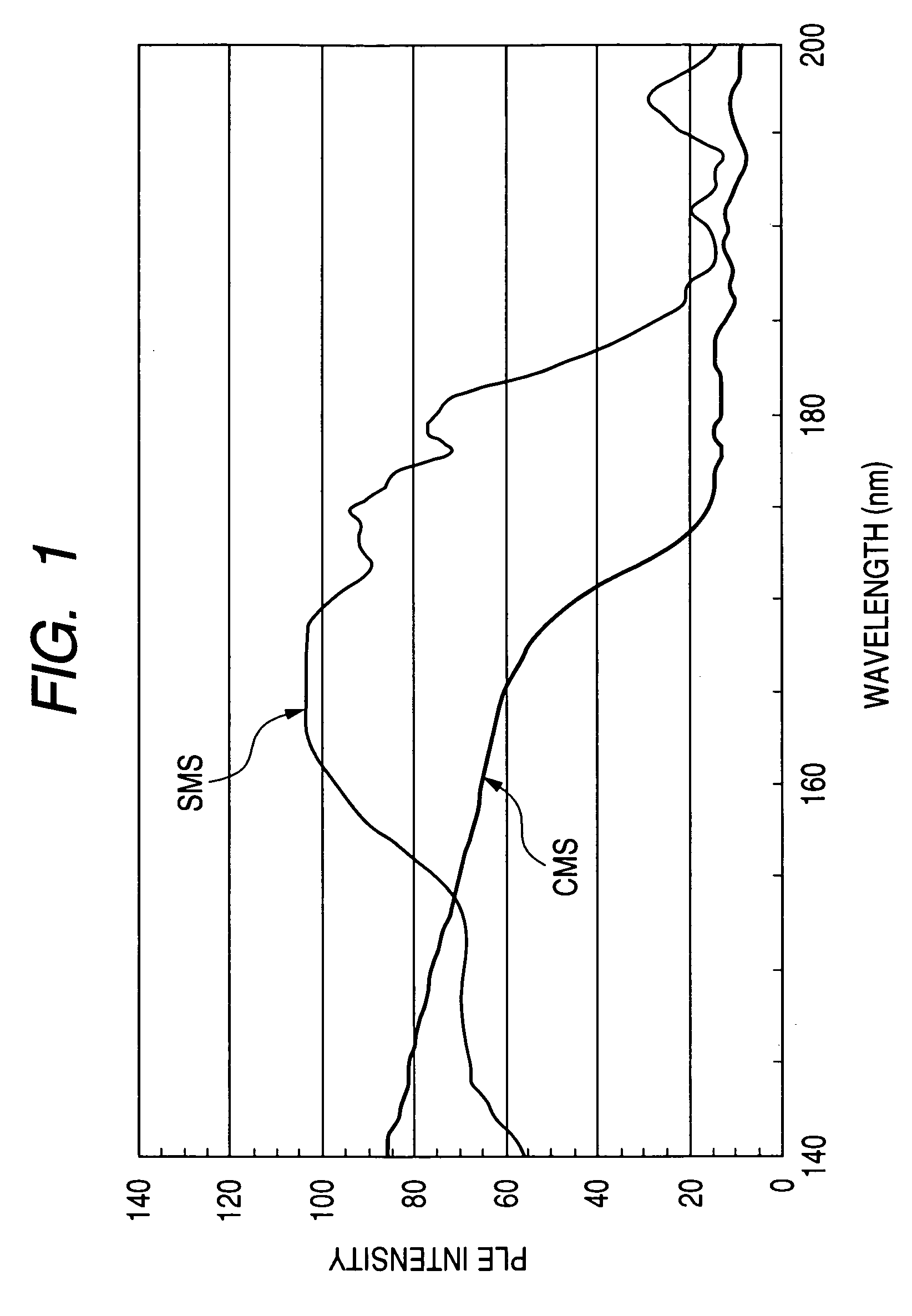
[0124]The prepared phosphor is a silicate phosphor (SMS) having a mole fraction of Mg slightly larger than the stoichiometric mole fraction (where b is 1 in the above formulae) and has a composition formula of Sr2.97Mg1.01Si2O8:Eu0.03. The actual composition formula of this phosphor is somewhat different from the composition formula just mentioned above, and the actual mole fraction typically of Sr is somewhat smaller than that in the compositional formula, since the mole fraction of Mg is larger than the stoichiometric mole fraction.
[0125]The phosphor was prepared in the following manner. Initially, 4.385 g (29.70 mmol) of SrCO3, 0.972 g (10.10 mmol) of MgCO3, 1.202 g (20.00 mmol) of SiO2, 0.0528 g (0.15 mmol) of Eu2O3, and 0.392 g (4.00 mmol) of NH4Br as a flux were weighed, were fully mixed in an agate morta...
third embodiment
[0134
[0135]Initially, a material phosphor was synthetically prepared for the preparation of a plasma display panel as the third embodiment of the present invention. The prepared phosphor is a silicate phosphor (SMS) having a mole fraction of Si larger than the stoichiometric mole fraction (where c is 1 in the above formulae) and has a composition formula of Sr2.99MgSi2.1O8.2:Eu0.01. The actual composition formula is somewhat different from the composition formula just mentioned above, and the actual mole fractions typically of Sr and Mg are somewhat smaller than the above composition, since the mole fraction of Si is larger than the stoichiometric mole fraction.
[0136]The phosphor was prepared in the following manner. Initially, 4.414 g (29.90 mmol) of SrCO3, 0.962 g (10.00 mmol) of MgCO3, 1.262 g (21.00 mmol) of SiO2, 0.0176 g (0.050 mmol) of Eu2O3, and 0.392 g (4.00 mmol) of NH4Br as a flux were weighed, were fully mixed in an agate mortar, the resulting mixture was charged into a ...
PUM
| Property | Measurement | Unit |
|---|---|---|
| mole fraction | aaaaa | aaaaa |
| mole fraction | aaaaa | aaaaa |
| wavelengths | aaaaa | aaaaa |
Abstract
Description
Claims
Application Information
 - R&D
- Intellectual Property
- Life Sciences
- Materials
- Tech Scout
- Unparalleled Data Quality
- Higher Quality Content
- 60% Fewer Hallucinations
Browse by: Latest US Patents, China's latest patents, Technical Efficacy Thesaurus, Application Domain, Technology Topic, Popular Technical Reports.
© 2025 PatSnap. All rights reserved.Legal|Privacy policy|Modern Slavery Act Transparency Statement|Sitemap|About US| Contact US: help@patsnap.com