Optical encoding method and encoder for optical code division multiplexing

a technology of optical code division and optical encoding, applied in the field of optical encoding methods and optical encoders for use in optical communication, can solve the problems of limiting the data transmission rate, reducing the number of codes available for multiplexing, and shortened chip intervals failing to produce matching increases in the number of codes. , to achieve the effect of increasing the number of optical communication channels

Inactive Publication Date: 2007-05-29
OKI ELECTRIC IND CO LTD
View PDF5 Cites 15 Cited by
  • Summary
  • Abstract
  • Description
  • Claims
  • Application Information

AI Technical Summary

Benefits of technology

[0013]A general object of the present invention is to increase the number of optica

Problems solved by technology

While this non-overlapping condition prevents interference, it also limits the data transmission rate.
The number of codes available for multiplexing is also limited.
This requirement constrains the pulse-train structure so that the shortened chip interval fails t

Method used


Image

  • Optical encoding method and encoder for optical code division multiplexing
  • Optical encoding method and encoder for optical code division multiplexing
  • Optical encoding method and encoder for optical code division multiplexing

Examples


first embodiment

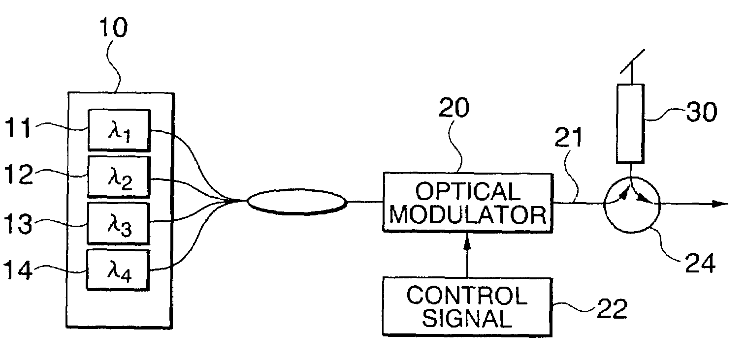
[0049]FIG. 1 shows the structure of an optical encoding system in which coding rules (1)–(5) are applied. The system employs a multiple-wavelength light source 10 including individual light sources 11, 12, 13, 14 that supply light of respective wavelengths λ1, λ2, λ3, λ4 to an optical modulator 20, which operates according to a control signal 22. The optical encoding system also includes an optical circulator 24 and an optical encoder 30. The wavelengths λ1, λ2, λ3, λ4 of the light sources 11–14 correspond to the center reflection wavelengths of CFBGs (described below) in the optical encoder 30.

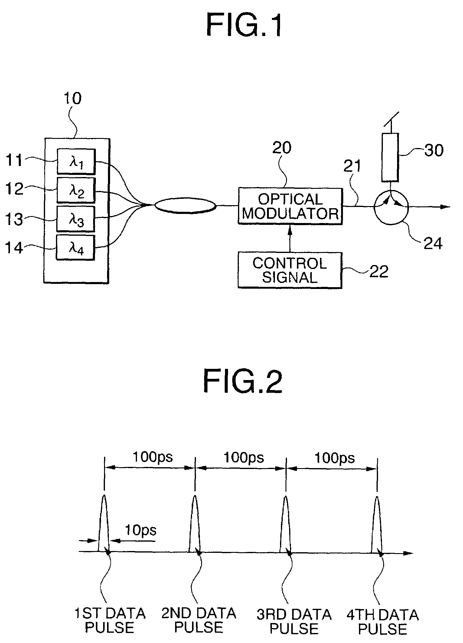
[0050]In the first embodiment, the data transmission rate is 10 Gbps. The wavelengths λ1, λ2, λ3, and λ4, output from the light sources 11–14 are combined, and the combined signal is input to the optical modulator 20. The optical modulator 20 modulates the combined signal according to the control signal 22, thereby generating a data signal 21, which is an arbitrary digital pulse signal with a...

second embodiment

[0063]In the first embodiment described above, although different encoded pulse trains (optical codes) output from the same optical encoder may overlap, interference is avoided because each pulse train is reassembled into a single pulse in the optical decoder. When the signals output from different optical encoders are multiplexed, however, further steps must be taken to ensure that pulse trains from different encoders do not interfere. In the second embodiment, two optical encoders are used and coding rule (6) is applied in addition to coding rules (1)–(5).

[0064]FIG. 7 shows the structure of an optical encoding system according to the second embodiment of the invention, omitting the optical circulators for simplicity. The system in the second embodiment includes the multiple-wavelength light source 10, optical modulator 20, and optical encoder 30 of the first embodiment and another similar optical modulator 20A and optical encoder 30A. Optical modulator 20 operates according to a c...


PUM


Abstract

A time-spreading and wavelength-hopping optical encoder spreads each pulse in a modulated optical pulse signal into a predetermined pulse train including pulses with different wavelengths. The last pulse in the pulse train is delayed from the first pulse in the pulse train by an interval that is longer than the pulse period of the modulated optical pulse signal. Interference is avoided by dividing the pulse train into successive delay groups that are equal in length to the pulse period of the modulated data pulse signal, and having each wavelength appear in only one delay group. If encoders producing differently structured pulse trains are used in an optical multiplexer, interference is avoided by having the same wavelength appear only at different positions within the delay groups of different pulse trains. Long delays can be used to multiplex a relatively large number of channels, even at high transmission rates.

Description

BACKGROUND OF THE INVENTION[0001]1. Field of the Invention[0002]The present invention relates to an optical encoding method and optical encoder for use in optical communication. More particularly, the present invention relates to optical encoding using a time-spreading wavelength-hopping code.[0003]2. Description of the Related Art[0004]Optical multiplexing raises the capacity of optical communication systems by enabling a single transmission path to carry a plurality of communication channels. Various optical multiplexing methods have been developed, starting with time division multiplexing and proceeding to wavelength division multiplexing, which provides more communication capacity. Even higher communication capacities are expected to be achievable by optical code division multiplexing (OCDM), which permits a plurality of communication channels to share the same time slot and the same wavelength group.[0005]A nine-chip, three-wavelength optical encoder using a time-spreading wave...

Claims


Application Information

Patent Timeline
IPC IPC(8): H04J14/02H04J14/08H04B10/00H04J14/00H04J14/04H04J14/06
CPCH04J14/005
Inventor NISHIKI, AKIHIKO
Owner OKI ELECTRIC IND CO LTD
Why Eureka
Try Eureka