System and method for implementing logic control in programmable controllers in distributed control systems

a distributed control system and logic control technology, applied in the field of industrial control and automation systems, can solve the problems of low flexibility and scalability extensive wiring requirements of centralized systems, and low flexibility of centralized control systems, so as to enhance modularity and reconfiguration ability, and eliminate expensive wiring

Active Publication Date: 2007-05-29
UNITRONICS 1989 RG
View PDF36 Cites 272 Cited by
  • Summary
  • Abstract
  • Description
  • Claims
  • Application Information

AI Technical Summary

Benefits of technology

[0029]The present invention answers these needs (1) by providing a unique control system and method for implementing a control program into a distributed control environment, without losing the advantages of a centralized system that relate to designing, right-sizing, programming, running, and synchronizing the application; (2) by replacing burdensome cabling with a reliable integrated wireless link, making both installation and future modifications easier; and (3) by providing an Internet-based communication platform.

Problems solved by technology

First, a centralized control system has lower flexibility and scalability.
Second, because a single processor (CPU) and a given amount of memory are used for the entire system, any future additional device, or any change in the system's configuration, must consider these limitations.
Third, the wiring requirements for a centralized system, wherein every device must be wired to a central controller, are extensive.
Although the use of remote I / O modules can reduce wiring requirements, adding more I / O modules to an existing controller does not add processing power and memory, which are usually fixed.
This would allow every condition to be set in one control program, but the wiring requirements in such a system would be much more extensive, and, importantly, the system would suffer from the lack of flexibility and scalability.
Were an existing device to need functional expansion, or were any additional device to need control in the future, it would require additional I / O modules to be added to the controller (if technically possible) and would require additional control programming as well, which would increase the workload for the fixed central processor and memory.
First, the demand for programmable logic controllers (PLCs) is growing as end users need more automation and are not able to afford machine downtime.
Nonetheless, while the drive towards distributed networking and decentralized control has important advantages, it also has significant drawbacks.
Maintenance is more complicated because global changes must be repeated in each component and because a single change requires modifications in more than one controller.
Further, although a decentralized control system is scalable, modular, and benefits from aggregated computing power, the workload between the processors typically is not balanced and depends on the way the designer chooses to distribute the code among the various processors.
Thus, the trend toward decentralized control opens new opportunities and creates important challenges.
The primary drawbacks of these existing solutions are (1) the need to develop support for the wireless modem (rarely a standard feature in PLCs); (2) the need for radio operation licensing in certain cases (especially for long range operations); (3) the relatively high cost of the devices (required for every PLC that needs to communicated wirelessly); and (4) the high operating costs that are required when using a public wireless network (such as a cellular network), whether such costs are fixed or based on traffic.
Therefore, extensive, and expensive, network wiring is required.

Method used


Image

  • System and method for implementing logic control in programmable controllers in distributed control systems
  • System and method for implementing logic control in programmable controllers in distributed control systems
  • System and method for implementing logic control in programmable controllers in distributed control systems

Examples


Embodiment Construction

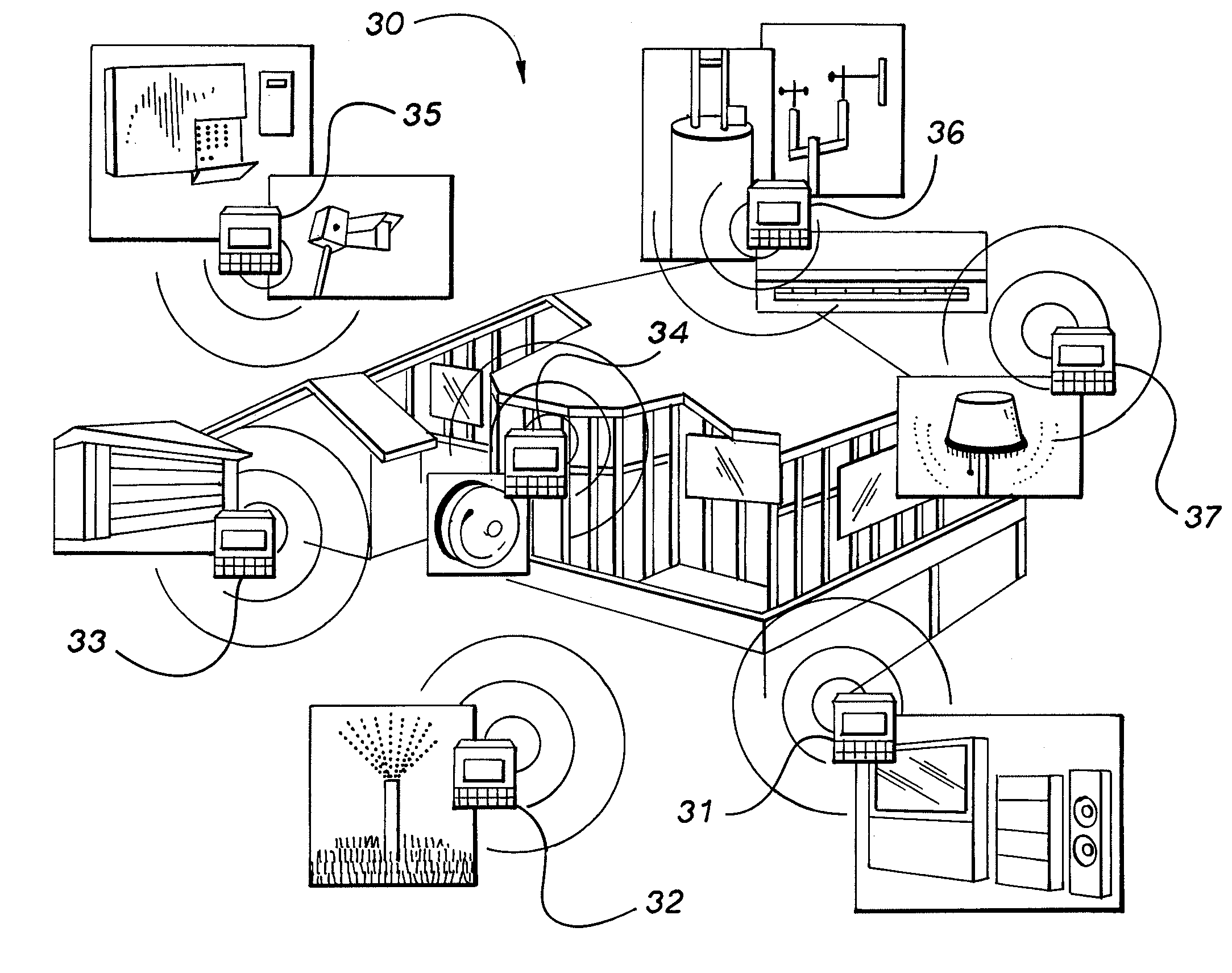
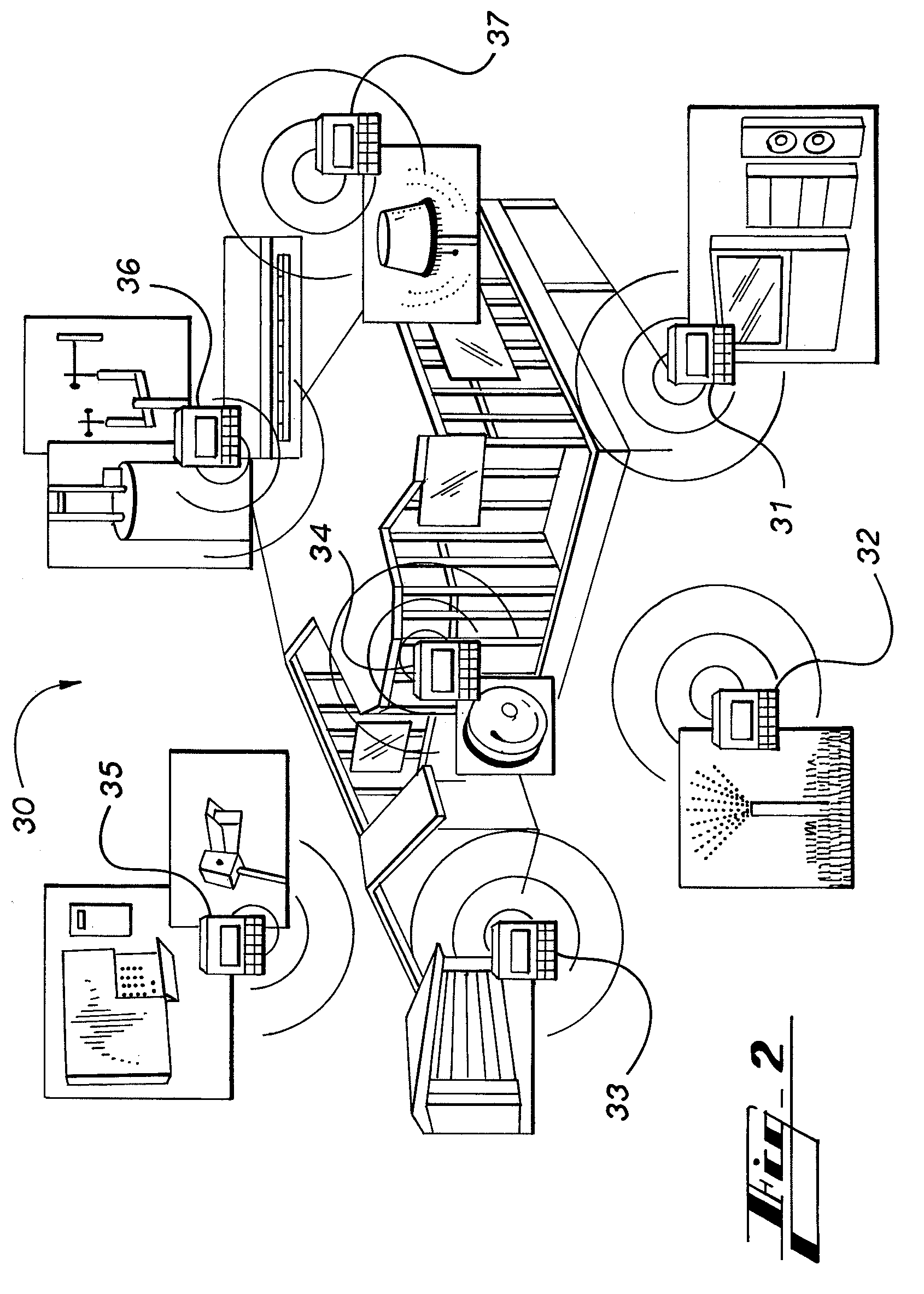
[0054]The present invention provides a system and a method for implementing a control program into a distributed control system, without losing the advantages of a centralized system in designing, right-sizing, programming, running, and synchronizing an application. The present invention also provides a reliable wireless link between the PLCs of a control system, thus eliminating the need for expensive communication wiring. In addition, the present invention provides an Internet-based communication platform for use in a control system.

[0055]Distributed / Centralized Control System.

[0056]Referring to FIG. 3, a control system 10 in accordance with the present invention is a centralized control system, where every I / O module 14 is like a small PLC and has its own processing and logic capability. In addition, the control system 10 may be seen as a distributed control system, i.e., a network 12 of practically independent PLCs 1–4 interconnected on a transmission medium 18, be it wired or w...


PUM


Abstract

The present invention provides a system and method for implementing logic control in programmable controllers in distributed control systems using a wired or wireless network. A software application is used to define the configuration of the network. Based on the network configuration, a compiler engine automatically assigns each statement of the control program to at least one programmable logic controller in the network. Each statement is then transmitted over a data transmission medium to the programmable logic controller assigned to the statement.

Description

RELATED APPLICATION[0001]This application claims the benefit of priority of U.S. provisional application Ser. No. 60 / 499,972, filed Sep. 3, 2003, which is relied on and incorporated herein by reference.FIELD OF THE INVENTION[0002]The present invention relates generally to industrial control and automation systems. More specifically, the present invention relates to a system and method for implementing logic control in programmable controllers in distributed control systems using a wired and / or wireless network.BACKGROUND OF THE INVENTION[0003]Distributed Control Systems.[0004]The concept of distributed industrial control systems, which have both a hardware and software component, is known in the art. Distributed control has been used since companies began installing programmable logic controllers (“PLCs”) to manage independent parts of a factory floor. PLCs are used in industrial control systems to provide coordinated control of equipment, devices, and processes. PLCs generally comp...

Claims


Application Information

Patent Timeline
Patent Type & Authority Patents(United States)
IPC IPC(8): G05B19/42G06F9/45G01M1/38G05B9/02G05B11/01G05B13/00G05B15/00G05B19/042G05B19/05G05B21/00G05D23/00
CPCG05B19/056
Inventor SHANI, HAIM
Owner UNITRONICS 1989 RG
Why Eureka
Try Eureka