Eureka AIR delivers breakthrough ideas for toughest innovation challenges, trusted by R&D personnel around the world.

Multi-cavity sample cylinder with integrated valving

a sample cylinder and multi-cavity technology, applied in the field of hydrocarbon fluid stream sampling and devices, can solve the problems of difficult to obtain a representative sample of a natural gas stream, depletion or accumulation of high molecular weight components, and accumulation of liquid in the sample container, so as to achieve easy and quick change and prevent contamination

Active Publication Date: 2007-06-05
MAYEAUX HLDG
View PDF14 Cites 5 Cited by
  • Summary
  • Abstract
  • Description
  • Claims
  • Application Information

AI Technical Summary

Benefits of technology

[0020]Unlike the prior art, the present invention provides a system for obtaining a representative gas sample with a sample cylinder which allows for sampling with nominal pressure differential during sampling, so as to avoid the Jule-Thomson cooling effect, and thereby prevent liquification of parts of the sample due to a drop to or below hydrocarbon dew point pressure.
[0021]The preferred embodiment of the present invention contemplates a sample container, which may be a cylinder, sphere, or other confiruation, having a flexible isolation barrier and integrated valving to provide a controlled ingress of sample gas at nominal pressure differential. Throttling of the gas is thereby avoided.
[0022]Further, the flexible isolation barrier may be fabricated of an inert, relatively inexpensive, and easily handled material, and the cylinder is thereby designed for easy repair or replacement of the barrier component, which replacement may be routinely performed to insure sample integrity. Further, barriers of different materials may be changed out as required, depending upon the material in contact with the barrier.
[0028]It is another object of the present invention to provide a sample cylinder having a flexible isolation barrier which is easily and quickly changed to prevent contamination, or to provide an alternative barrier material as required.
[0029]Lastly, it is an object of the present invention to provide a method and system for sampling gas at or near the hydrocarbon dew point temperature which provides an accurate sample, while avoiding fluid formation due to gas throttling.

Problems solved by technology

It is well known by the natural gas industry that it is very difficult to obtain a representative sample of a natural gas stream, which is at or below its hydrocarbon dew point temperature (H.C.D.P.).
Major problems with spot and composite sampling are the accumulation of liquid in the sample container during the “purging” phase and depletion or accumulation of high molecular weight components during the sample filling phase.
Several problems are associated with the use of this type of hardware.
One such problem is that the friction of the piston seals can cause a pressure difference of 20 to 30 PSI between the two cylinder cavities.
The second is that the piston seals can harbor contaminates from previous samples.
Cleaning is very difficult and time consuming.
The entry ports and valving designs in the end caps require purging and also represent a source of sample composition distortion during the purging phase.
Constant volume cylinders are difficult to clean between samples as recommended by API and GPA standards.
It is also difficult if not impossible to verify if they are indeed clean after the cleaning process.
Further, prior art valves typically installed on sample cylinders are prone to becoming damaged during transportation.
Valve stem packing leaks are also a common problem.
Vibration and rough handling during transportation an also result in valves becoming partially opened thereby allowing fluids to leak out.
The prior art has therefore failed to provide a constant volume-type sample cylinder which is easy to clean and service, reliable in operation, and effective in preventing throttling of the sample gas.

Method used


Image

  • Multi-cavity sample cylinder with integrated valving
  • Multi-cavity sample cylinder with integrated valving
  • Multi-cavity sample cylinder with integrated valving

Examples


Embodiment Construction

Sample Cylinder Device

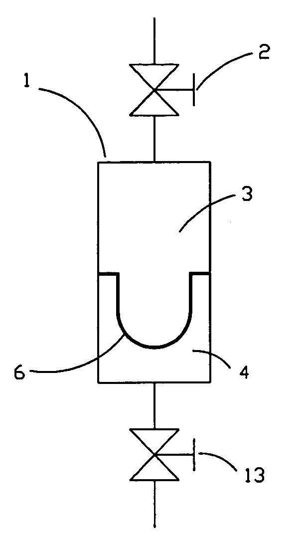
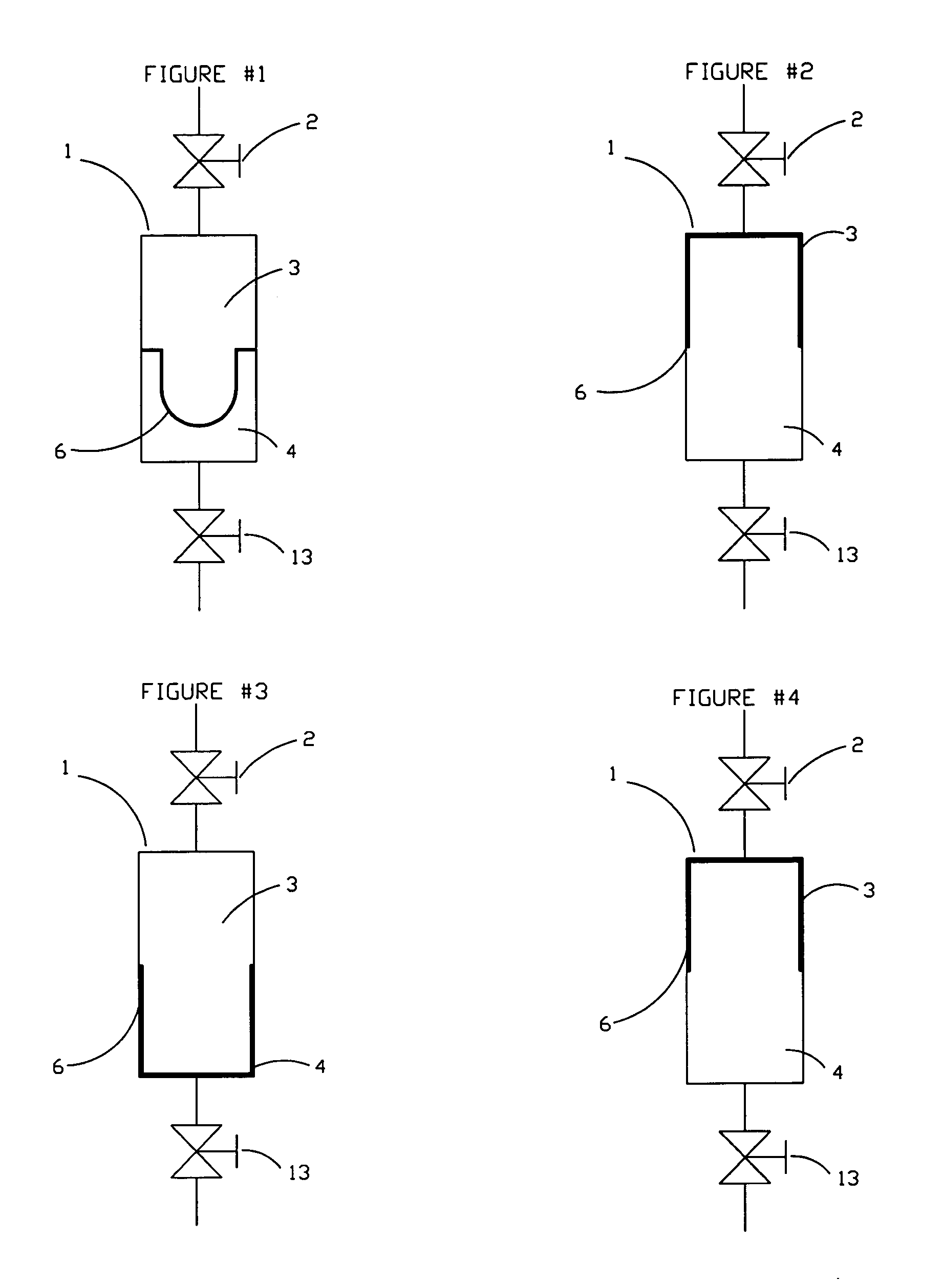
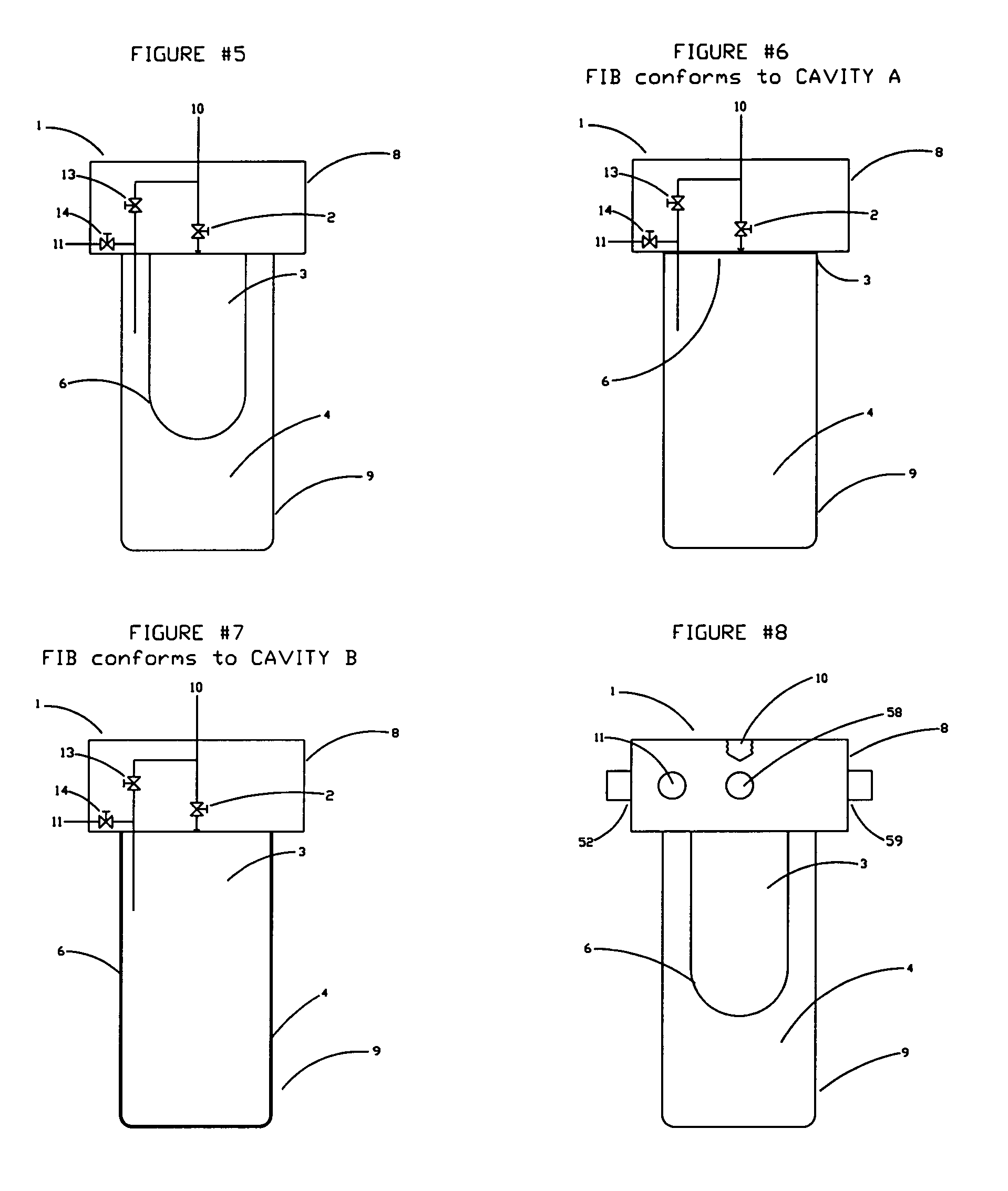
[0070]Referring to FIGS. 1–4, the first invention consists of a cylinder 1 forming the body of the unit, the cylinder having a chamber formed therein having a flexible isolation barrier 6 attached therein (FIG. 1). Flexible isolation barrier 6 divides the internal volume of the cylinder 1 into two sections or cavities (cavity 3 and cavity 4). Inlet valve 2 and purge valve 13 installed at each end of the cylinder 1 provide fluid communication between each of the two cavities and the exterior of the cylinder 1.

[0071]By first opening inlet valve 2 and then allowing a source of gas (pre-charge gas) to flow into cavity 4 by way of purge valve 13, the flexible isolation barrier 6 is moved toward cavity 3 thereby displacing the residual gas in cavity 3. When all of the gas is displaced, the flexible isolation barrier 6, being a thin and flexible material, conforms to the interior of the section of sample container formerly comprising cavity 3.

[0072]The volume of cavit...


PUM


Abstract

A system for obtaining a representative sample of a natural gas stream, particularly a stream which is at or below its hydrocarbon dew point temperature (H.C.D.P.). The preferred embodiment of the present invention contemplates a sample cylinder having a flexible isolation barrier and integrated valving to provide a controlled ingress of sample gas at nominal pressure differential. The system thereby avoids throttling of the sample gas and the inherent cooling problems associated therewith when the stream is at or below hydrocarbon dew point temperature. The flexible isolation barrier of the present invention is relatively inexpensive and is configured for quick and easy replacement, which may be routinely performed to insure sample integrity. Alternative embodiments of the invention contemplate a spherical sample cylinder configuration with flexible isolation barrier, as well as an improvement for piston-type sample cylinders to provide constant sample pressure.

Description

PRIORITY CLAIM[0001]The present application claims the benefit of U.S. Provisional Patent Application No. 60 / 400,736, having a filing date of Aug. 2, 2002 listing inventor Donald A. Mayeaux.TECHNICAL FIELD OF THE INVENTION[0002]The present invention relates to sampling of hydrocarbon fluid streams and devices therefore, and in particular to a system particularly suitable for obtaining a representative sample of a natural gas stream, which is at or below its hydrocarbon dew point temperature (H.C.D.P.). The preferred embodiment of the present invention contemplates a sample cylinder having a flexible isolation barrier and integrated valving to provide a controlled ingress of sample gas at nominal pressure differential. The system thereby avoids throttling of the sample gas and the inherent cooling problems associated therewith when the stream is at or below hydrocarbon dew point temperature. The flexible isolation barrier of the present invention is relatively inexpensive and is conf...

Claims


Application Information

Patent Timeline
IPC IPC(8): G01N1/22
CPCG01N1/2247G01N33/22G01N2001/2071G01N2001/2238
Inventor MAYEAUX, DONALD P.
Owner MAYEAUX HLDG
Why Eureka
Eureka Blog
Learn More