
Engine timing control with intake air pressure sensor

a technology of intake air pressure sensor and timing control, which is applied in the direction of machines/engines, liquid/fluent solid measurement, process and machine control, etc., can solve the problems of increasing costs and complexity of engine systems, limiting the application of this technology in price sensitive markets, and reducing the complexity of fuel injection systems. , the effect of low cost and low complexity

Inactive Publication Date: 2007-06-05
ELECTROJET TECH INC
View PDF31 Cites 42 Cited by
  • Summary
  • Abstract
  • Description
  • Claims
  • Application Information

AI Technical Summary

Benefits of technology

This approach reduces sensor complexity and cost, enabling more accurate and efficient fuel injection control with fewer components, allowing for easier integration of fuel injection technology into existing engines without the need for extensive redesign or additional hardware, while providing redundancy for reliable operation.

Problems solved by technology

The trend towards fuel injection has not been without added costs, and as such has limited the applications of this technology in price sensitive markets.
All of these components add costs and complexity to the engine system.
Many manufacturers simply cannot be competitive with the added costs of fuel injection in their product line, and as such are delaying its implementation until emissions regulations mandate its use.
This measurement process can be quite complex.
This challenge can be complicated further by monitoring intake air pressure in engines with few cylinders.
However, if few cylinders are present as in small engines, there will be fewer intake events per crankshaft rotation and large intake air pressure fluctuations will be apparent.
If the average intake pressure were to be obtained, it will not be an accurate indication of actual cylinder intake air pressures due to these fluctuations.
Unfortunately, the crankshaft rotates twice for a complete 720° cycle in four stroke engines.
These systems cannot predict engine timing for fuel injection purposes due to crankshaft acceleration and deceleration.
Due to its nature, a camshaft position sensor is not as accurate as a crankshaft position sensor and therefore they are typically used in combination.
These multiple parts all add in the cost of fuel injection implementation.
Using a crankshaft trigger alone does not allow an engine to be timed on a 720° cycle (in four stroke applications).

Method used


Image

  • Engine timing control with intake air pressure sensor
  • Engine timing control with intake air pressure sensor
  • Engine timing control with intake air pressure sensor

Examples


Embodiment Construction

)

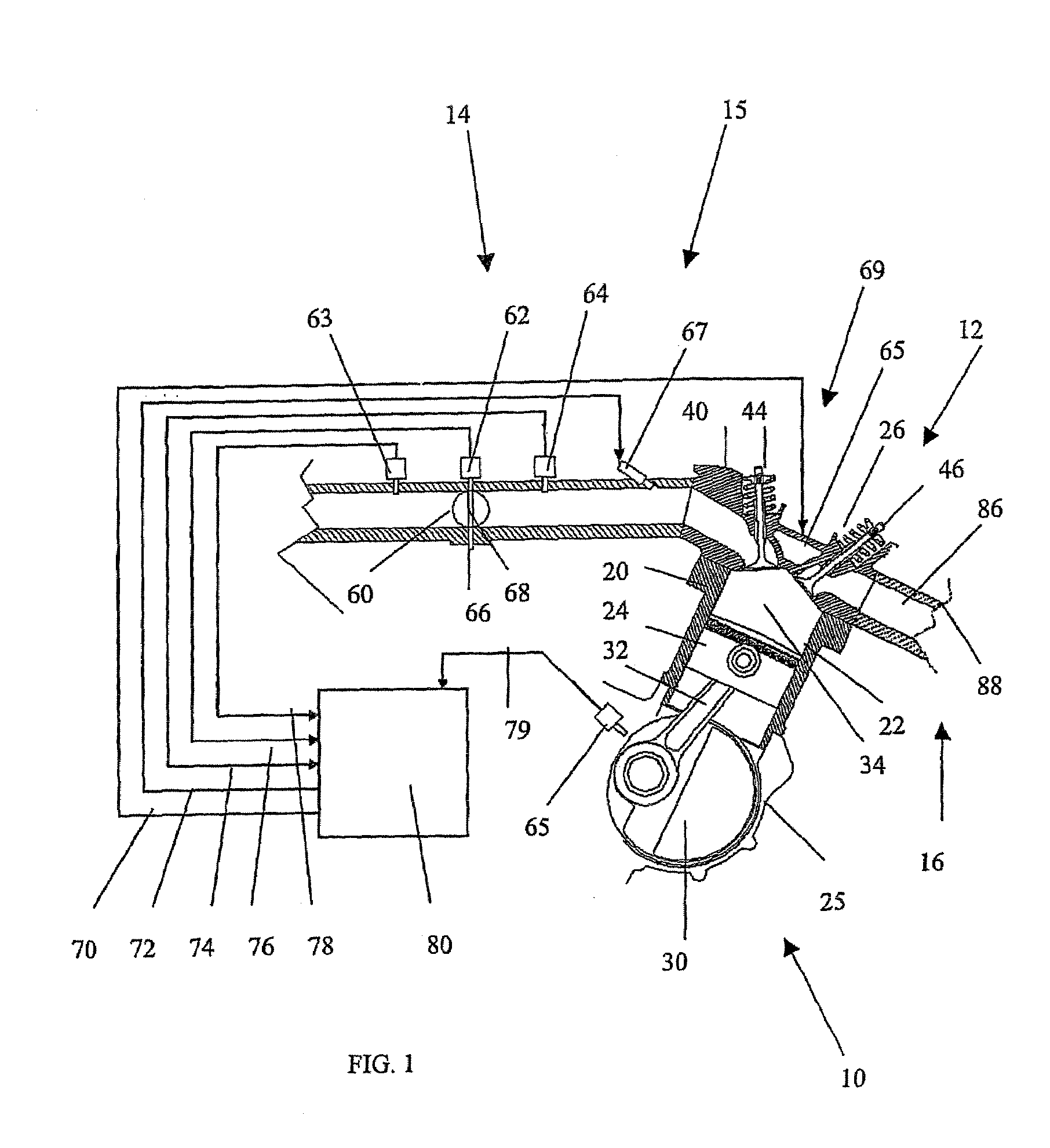
[0114]FIG. 1 shows an internal combustion engine 10 for use in an All Terrain Vehicle (ATV, or Four-wheeler). The present invention may also find utility in applications using internal combustion engines, such as, for example but without limitation, personal watercraft, small jet boats, off-road vehicles, heavy construction equipment, motorcycles, lawn tractors, and gas powered yard implements.

[0115]As used throughout this description, the terms “forward”, “front” and “fore” mean at or to the forward side of exhaust system 16, and the terms “rear”, “reverse” and “rearwardly” mean at or to the opposite side of the front side, unless indicated otherwise.

[0116]The engine 10 operates on a four-stroke combustion cycle. As shown in FIG. 1, the engine 10 includes a cylinder block 20, which defines a cylinder bore 22. In the illustrated embodiment, the engine 10 is of the single cylinder type.

[0117]It is to be noted that the engine may be of any type (V-type, Inline, W-type), may have othe...


PUM


Abstract

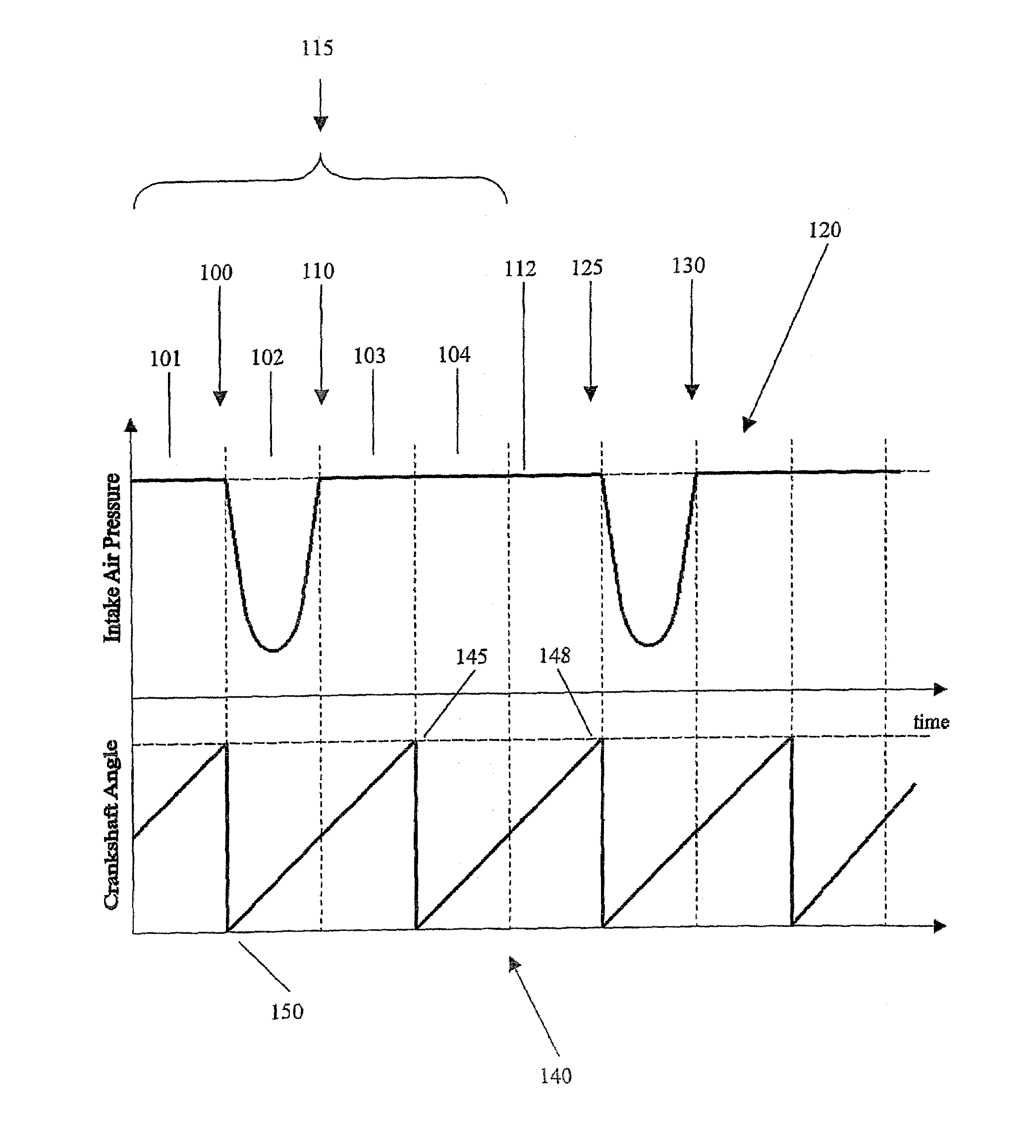
An engine control apparatus is disclosed for determining crankshaft position and engine phase of an internal combustion engine through monitoring intake air pressure fluctuations. The opening of the intake valve is mechanically linked to the crankshaft position of an engine. When the intake valve opens it creates air pressure fluctuations in the air induction system of the engine. The control apparatus is configured to determine intake air pressure fluctuations indicative of an intake air event and thus a particular crankshaft position, and their corresponding period of the engine cycle. The controller then uses this information to determine crankshaft speed and position for the purpose of fuel injection and ignition timing of the internal combustion engine. Engine phase is also determined on four-stroke engines. The engine may also include a crankshaft position sensor in combination with monitoring intake air pressure fluctuations to increase resolution in determination of crankshaft position. A circuit is provided for simultaneously measuring intake temperature using a single bridge type pressure sensor in order to calculate air mass flow rate.

Description

CROSS-REFERENCE TO RELATED APPLICATIONS[0001]This application is a continuation-in-part of PCT application No. PCT / US / 2004 / 026093 filed Aug. 12, 2004, which, in turn, claims priority to U.S. Pat. No. 6,804,997 which issued on Oct. 19, 2004.BACKGROUND OF THE INVENTION[0002]1. Field of the Invention[0003]The present invention is directed to an intake air pressure sensor assembly for an internal combustion engine, and in particular, a fuel-injected engine that communicates with a controller for controlling the fuel injectors and ignition timing based on detected air pressure fluctuations.[0004]2. Background Art[0005]In all fields of engine design there is emphasis on fuel economy, engine performance, and most notably, engine-out emissions. Increased emissions restrictions have led to the necessity of a more accurate fuel metering process. Fuel injection systems have emerged as an accurate way to control the air and fuel mixture in an internal combustion engine and thus keep emissions l...

Claims


Application Information

Patent Timeline
Patent Type & Authority Patents(United States)
IPC IPC(8): F02P5/10F02D41/18F02D41/22F02D41/34
CPCF02D41/009F02D41/0097F02D41/18F02D41/222G01F1/34F02D2041/227F02D2200/0406F02D2400/18G01L9/06G01L19/0092
Inventor SCHWULST, KYLE E. E.PATTANTYUS, TAMAS I.
Owner ELECTROJET TECH INC
Learn More