Film applicator tool with arcuate edges

a film applicator and edge technology, applied in the field of tools, can solve the problems of forming bubbles or folds in the film, difficult application of any of these films, laborious process, etc., and achieve the effect of preventing tearing or abrading the film during application, ensuring the effect of adhesion and flexibility

a film applicator and edge technology, applied in the field of tools, can solve the problems of forming bubbles or folds in the film, difficult application of any of these films, laborious process, etc., and achieve the effect of preventing tearing or abrading the film during application, ensuring the effect of adhesion and flexibility

US7225848B2Inactive Publication Date: 2007-06-05WILLIAMS ROBERT D

Image

  • Film applicator tool with arcuate edges
  • Film applicator tool with arcuate edges
  • Film applicator tool with arcuate edges

Examples


Embodiment Construction

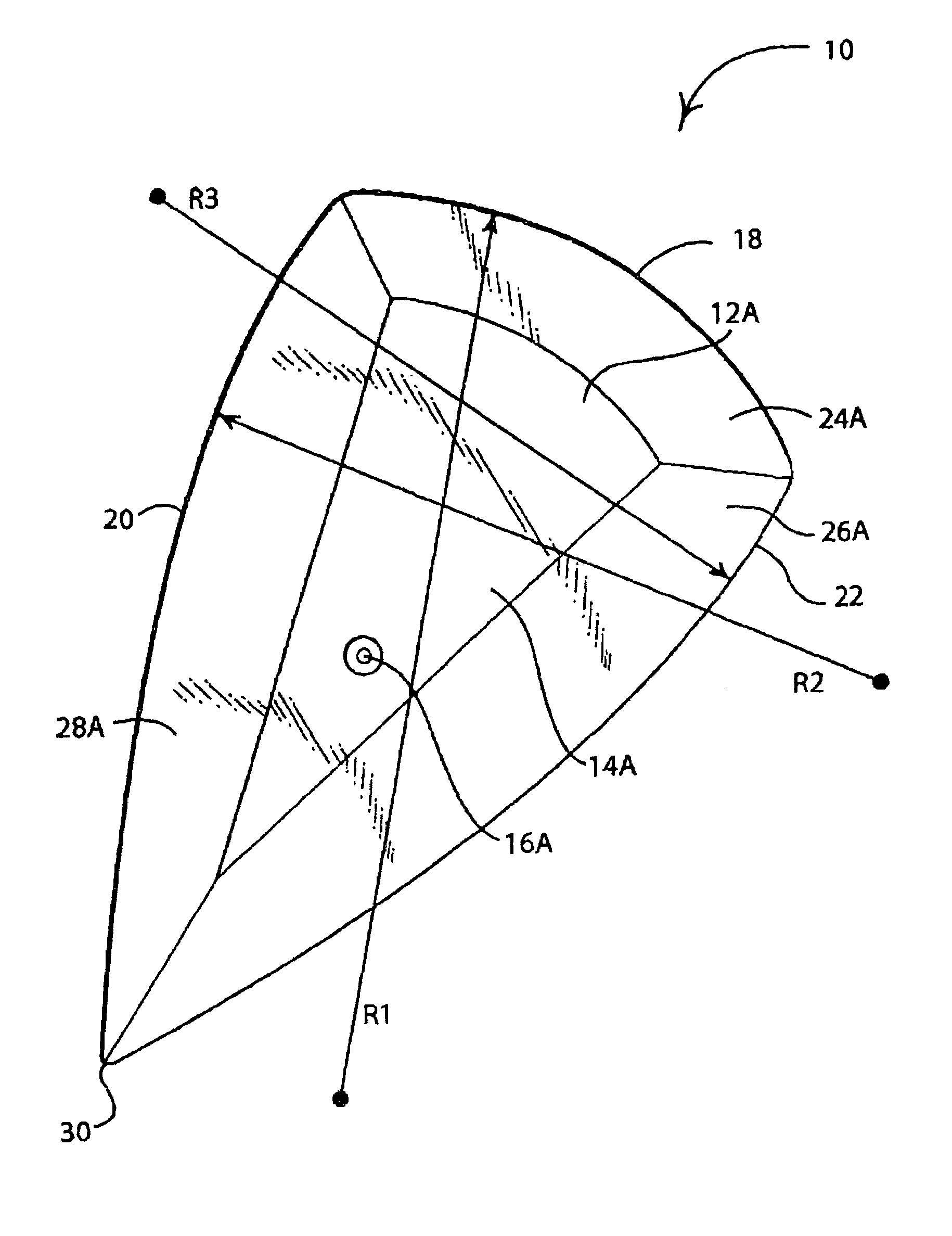
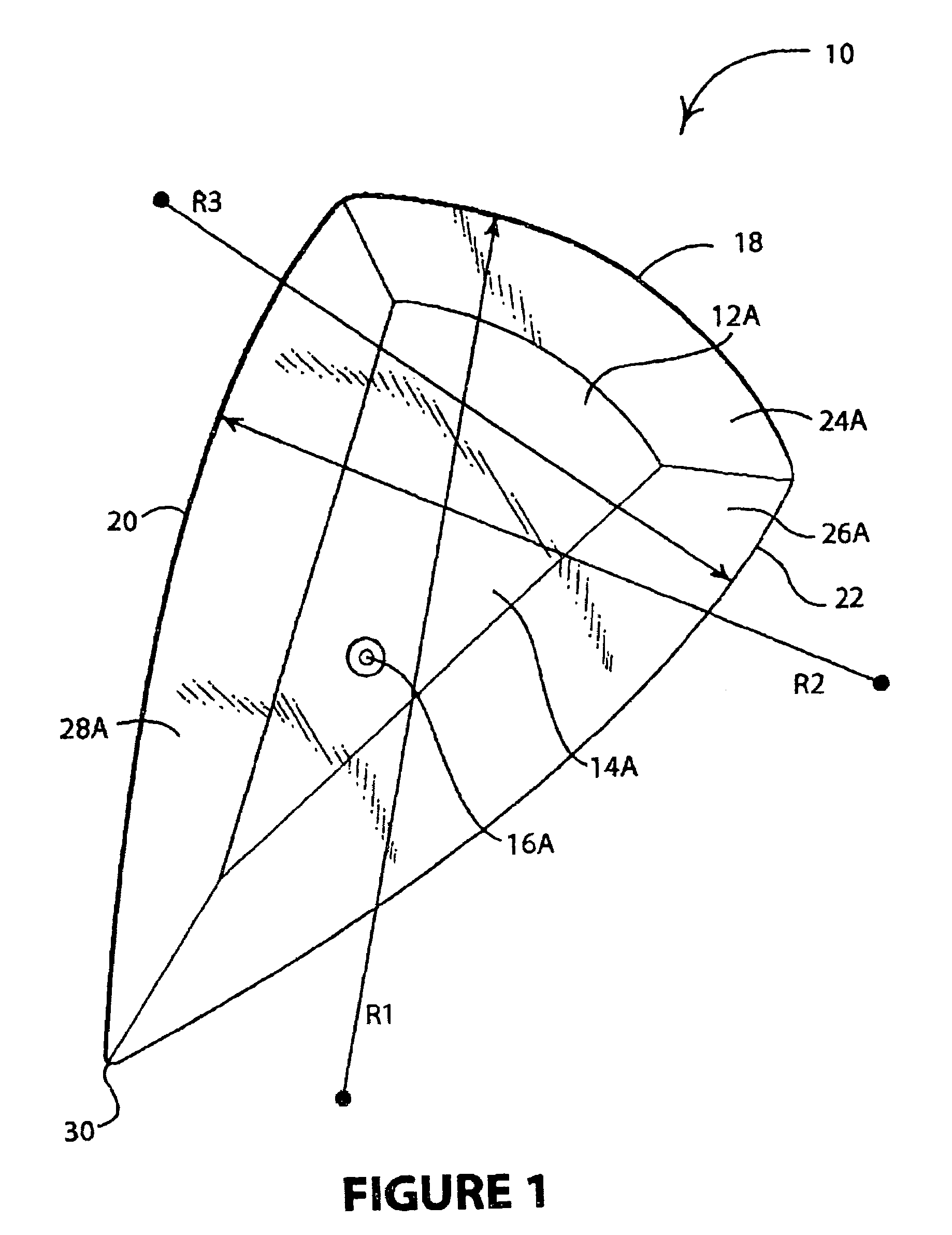
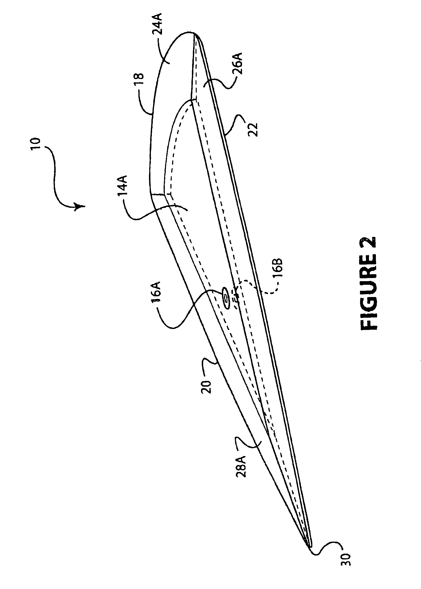
[0031]Firstly, although the embodiment described above is bilaterally symmetric, it may be described as having upper and lower surfaces or first and second surfaces, even though these surfaces may be essentially identical. Where used, the expression “and / or” is used in the sense of A, B or A+B. The term “arcuate” is used to mean an edge or contour having a uniform radius of convex curvature.

[0032]Turning now to the drawings, FIG. 1 shows a generally triangular applicator tool 10 having a first side 12A and a second side (not visible here) 12B. Each side has a raised or thicker central portion 14A (and 14B, not visible here). Mold marks 16A and 16B are left on the tool by the preferred dual cavity molding process, which easily produces a tool having bilateral symmetry. Arcuate edges 18, 20 and 22 have at least two different radii of curvature R1, R2 and R3, respectively, as indicated in FIG. 1. Depending upon the type of application, these radii can range from about to about inches. ...


PUM

PropertyMeasurementUnit
widthaaaaaaaaaa
radiusaaaaaaaaaa
acute angleaaaaaaaaaa

Abstract

Film applicator tools are provided which have at least two arcuate edges which are sufficiently flexible and resilient to permit application of adhesive films to smooth surfaces without leaving air bubbles, creases or other defects. The tools are molded of polymeric materials which have hardness values effective to permit the application of smooth and uniform pressure without tearing or abrading the films.

Description

BACKGROUND OF THE INVENTION[0001]1. Field of the Invention[0002]The present invention pertains to tools for applying films to smooth surfaces, e.g. adhesive films to glass surfaces, in particular solar films for automotive windows.[0003]2. Discussion of Relevant Art[0004]Various types of films for covering or altering many types of surfaces have been used for many years. Wallpaper and other wallcovering materials such as self-adhesive films or films which adhere to surfaces through static electrical effects are one category. An increasing variety of films are being used to decorate or alter the light transmission properties of glass surfaces, flat and curved, residential / commercial through auto safety glazing. Some of these films are used to “darken” the glass by reducing light transmission; others affect work or living space environments by controlling heat gain and reducing solar radiation-caused fading, while other films may serve additional functions of enhancing safety and secu...

Claims


Application Information

Patent Timeline
05 Jun 2007
Publication
US7225848B2
IPC
B32B37/00
CPC
B29C63/0047; B44C1/10; C03C17/001; Y10T156/18; Y10T156/1788
Inventors
WILLIAMS, ROBERT D