Multi-tube fixed-bed reactor, especially for catalytic gas phase reactions

Inactive Publication Date: 2007-06-05
BASF SE
View PDF13 Cites 56 Cited by
  • Summary
  • Abstract
  • Description
  • Claims
  • Application Information

AI Technical Summary

Benefits of technology

[0010]It is an object of the present invention to provide a reactor which makes possible a more uniform temperature distrib

Problems solved by technology

However, the high enthalpy of reaction liberated can, in particular, lead to the catalyst sintering or melting or becoming inactive in individual tubes in the case of deviations from the prescribed temperature range.
This is associated with considerable risks for the plant.
This results in formation of increased amounts of by-products which reduce the yield and have to be separated from the resulting phthalic anhydride in later purification steps and have to be disposed of.
Such a hot spot is desirable in principle but problems occur if the hot spot temperat

Method used


Image

  • Multi-tube fixed-bed reactor, especially for catalytic gas phase reactions
  • Multi-tube fixed-bed reactor, especially for catalytic gas phase reactions
  • Multi-tube fixed-bed reactor, especially for catalytic gas phase reactions

Examples


Example

Example 1

Preparation of PA Using a Reactor According to the Present Invention

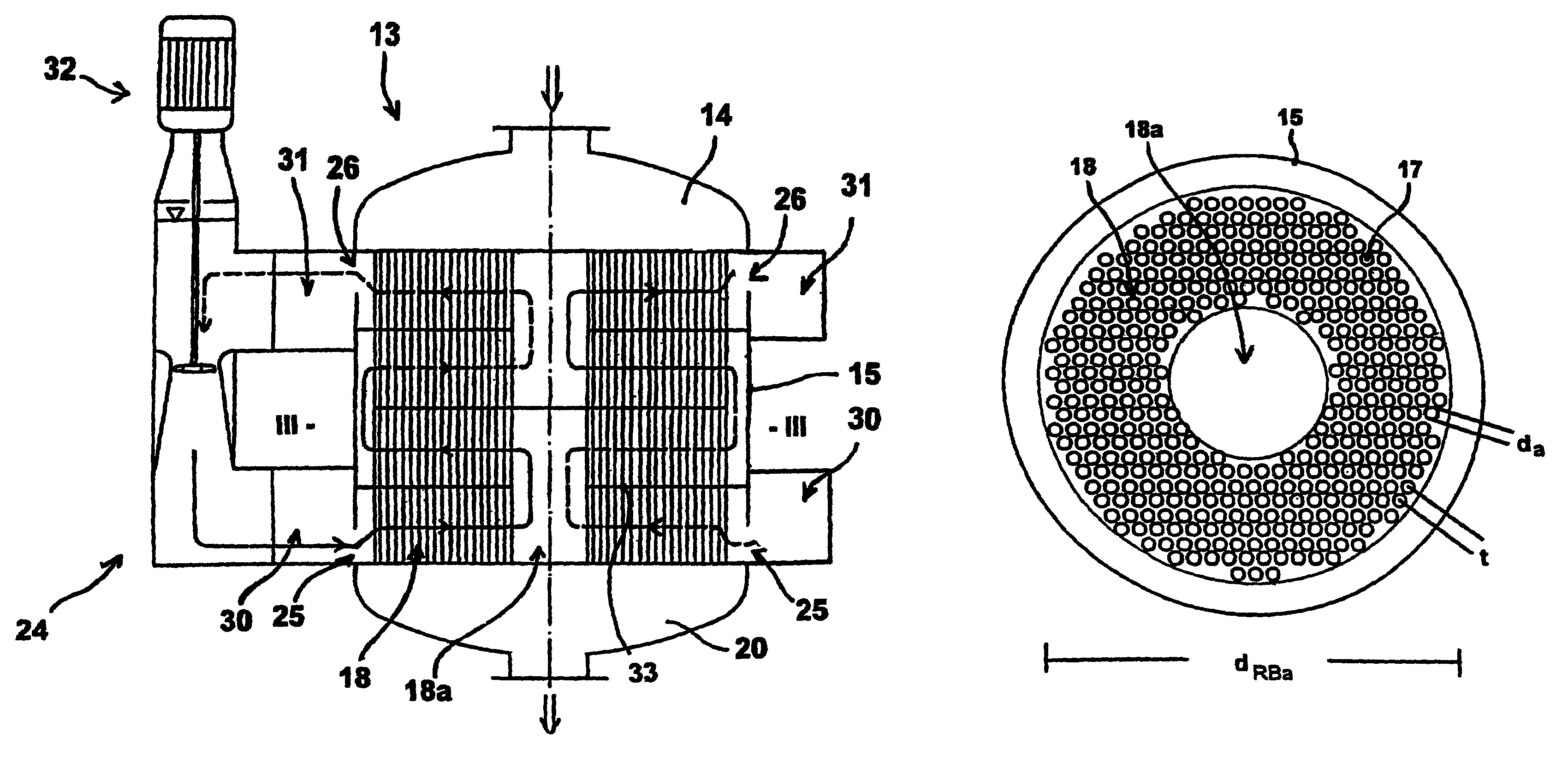
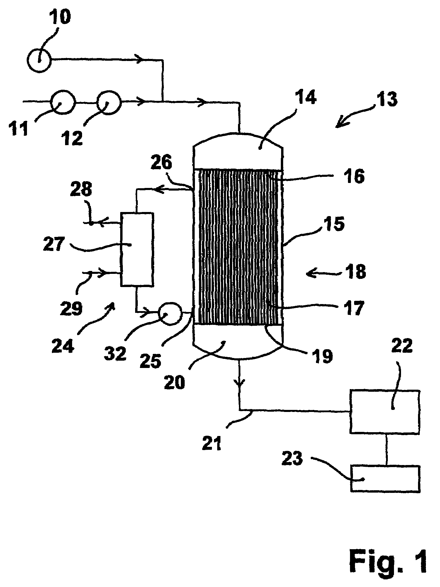
[0060]A tube bundle having an external diameter of dRBa=5.435 m was located in the reactor of the present invention. The tube bundle consisted of about 14,000 catalyst tubes made of steel which each had a length of 3.5 m and an external diameter da was thus 1.3793. 4 standard m3 / h of air having a loading of 98.5% purity by weight o-xylene of 90 g / standard m3 were passed through the tube from the top downward. The catalyst tubes were filled in a manner to provide for two catalyst zones with different activity. Firstly, catalyst II was filled into each tube to a total height of (as measured from the bottom of the tubes) of 1.3 m. Then a total 1.7 m catalyst I was filled into each tube on top of the catalyst II layer.

[0061]The heat transfer medium used was a salt melt of KNO3, NaNO2 and NaNO3 which was passed through the reactor at 348.9° C. and a flow rate of 11,000 m3 per hour. The exit temperature of the me...

Example

Example 2

Comparative Example

Preparation of PA Using a Reactor According to the Prior Art

[0064]A tube bundle having an external diameter of dRBa=5.021 m was located in the reactor of the prior art. The tube bundle consisted of about 14,000 catalyst tubes made of steel which each had a length of 3.5 m and an external diameter da=30 mm. The tube spacing t was 38 mm; the ratio t / da was thus 1.267. Again, filling of the catalyst tubes—as described in example 1—provided for two zones with different catalyst activity.

[0065]4 standard m3 / h of air having a loading of 98.5% purity by weight o-xylene of 90 g / standard m3 were again passed through the tube from the top downward. The heat transfer medium used was a salt melt of KNO3, NaNO2 and NaNO3 as in the example according to the present invention.

[0066]The inflow temperature of the melt was 345.9° C.; 6200 m3 of melt per hour were passed through the reactor. The exit temperature of the melt was 349.7° C. The hot spot temperature of the salt ...


PUM

PropertyMeasurementUnit
Lengthaaaaaaaaaa
Lengthaaaaaaaaaa
Lengthaaaaaaaaaa

Abstract

A multitube fixed bed reactor and the use of such a reactor for carrying out catalytic gas-phase reactions, in particular for carrying out exothermic and endothermic catalytic gas-phase reactions such as the preparation of phthalic anhydride (PA), acrylic acid, methacrylic acid (MAA), acrolein, maleic anhydride (MA), glyoxal, phosgene, hydrocyanic acid or vinyl formamide (VFA). In a relatively large multitube reactor in which a large amount of heat of reaction is generated owing to the numerous catalyst tubes (17) and has to be removed, it is proposed that the ratio of tube spacing t to external tube diameter da be made dependent on the reactor diameter or on the external tube bundle diameter dRBa. At an external diameter of the catalyst tube bundle (18) of more than 4 meters, a ratio of tube spacing d to external tube diameter da of at least 1.3 is preferred.

Description

[0001]The present invention relates to a multitube fixed bed reactor and the use of such a reactor for carrying out catalytic gas-phase reactions, in particular for carrying out exothermic and endothermic catalytic gas-phase reactions such as the preparation of phthalic anhydride (PA), acrylic acid (AA), methacrylic acid (MAA), acrolein, maleic anhydride (MA), glyoxal, phosgene, hydrocyanic acid or vinyl formamide (VFA).BACKGROUND OF THE INVENTION[0002]In the chemical industry, multitube reactors are usually used for carrying out catalytic gas-phase reactions over fixed-bed catalysts.[0003]Multitube reactors usually comprise a catalyst tube bundle made up of numerous parallel catalyst tubes and arranged within an outer wall. The catalyst tubes, which usually contain supported or unsupported catalysts, have their open ends fixed so as to form a seal to tube plates and each of them opens into a cap connected to the outer wall at the upper or lower end. Apart from supported catalysts, ...

Claims


Application Information

Patent Timeline
IPC IPC(8): B01J8/06B01J19/00B01J19/24C07C45/35C07C45/38H01Q21/08
CPCB01J8/067B01J19/0013B01J19/2425C07C45/35C07C45/38C07C47/22C07C47/127B01J2208/00212B01J2208/00221B01J2208/00256B01J2219/00094B01J2219/00103B01J8/00
Inventor OLBERT, GERHARDCORR, FRANZREUTER, PETERWAMBACH, LUDWIGHAMMON, ULRICH
Owner BASF SE
Why Eureka
Try Eureka