Very low emission hybrid electric vehicle incorporating an integrated propulsion system including a fuel cell and a high power nickel metal hydride battery pack

a hybrid electric vehicle and fuel cell technology, applied in the direction of hydrogen, gas pressure propulsion mounting, power supply for propulsion, etc., can solve the problems of increasing the distance between the global energy system and the planet, increasing the cost of hydrogen, and inherently low cost fuel. , to achieve the effect of increasing the amount of power on demand and extending the rang

Inactive Publication Date: 2007-06-05
CHEVRON TECH VENTURES
View PDF5 Cites 40 Cited by
  • Summary
  • Abstract
  • Description
  • Claims
  • Application Information

AI Technical Summary

Benefits of technology

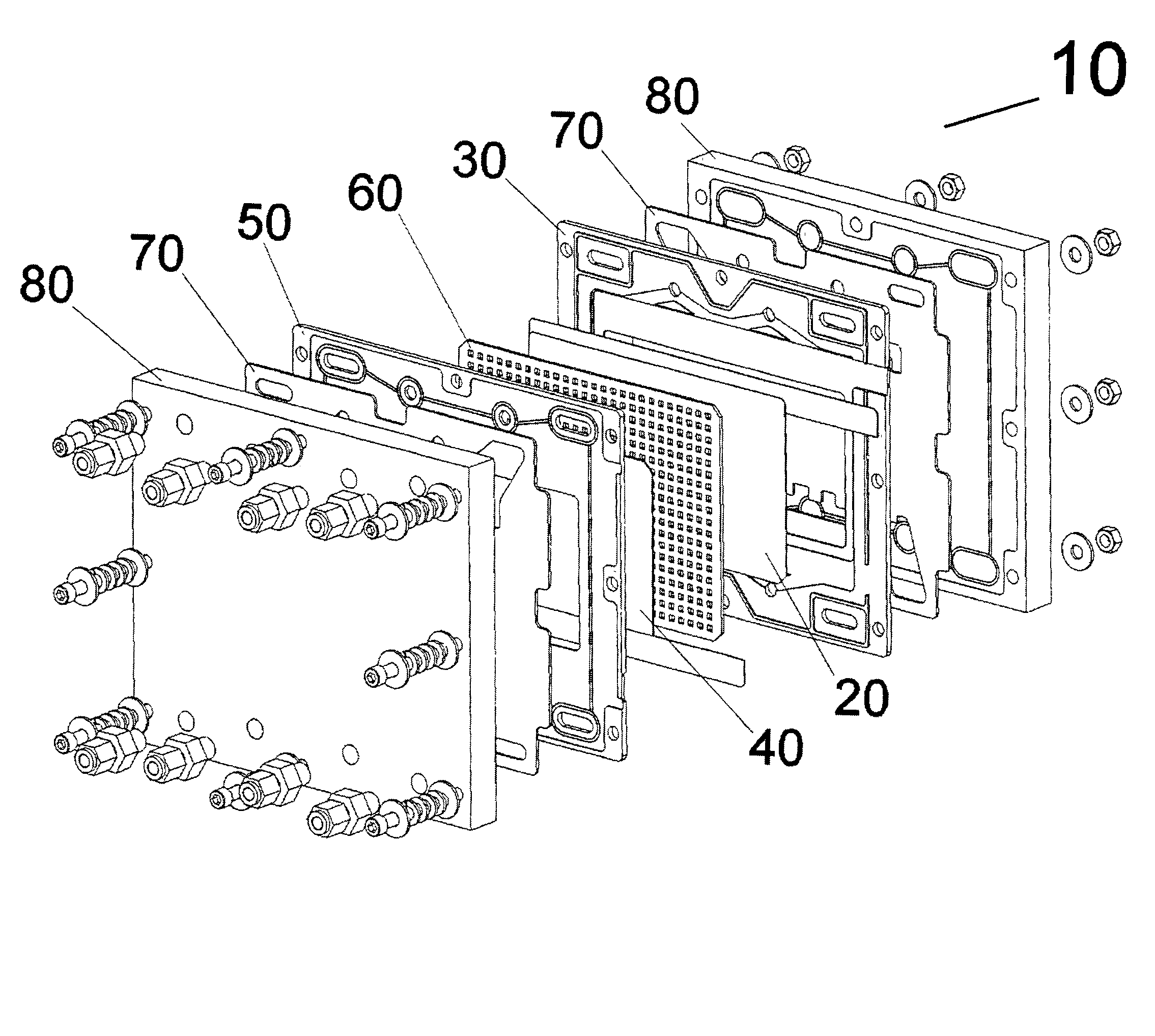
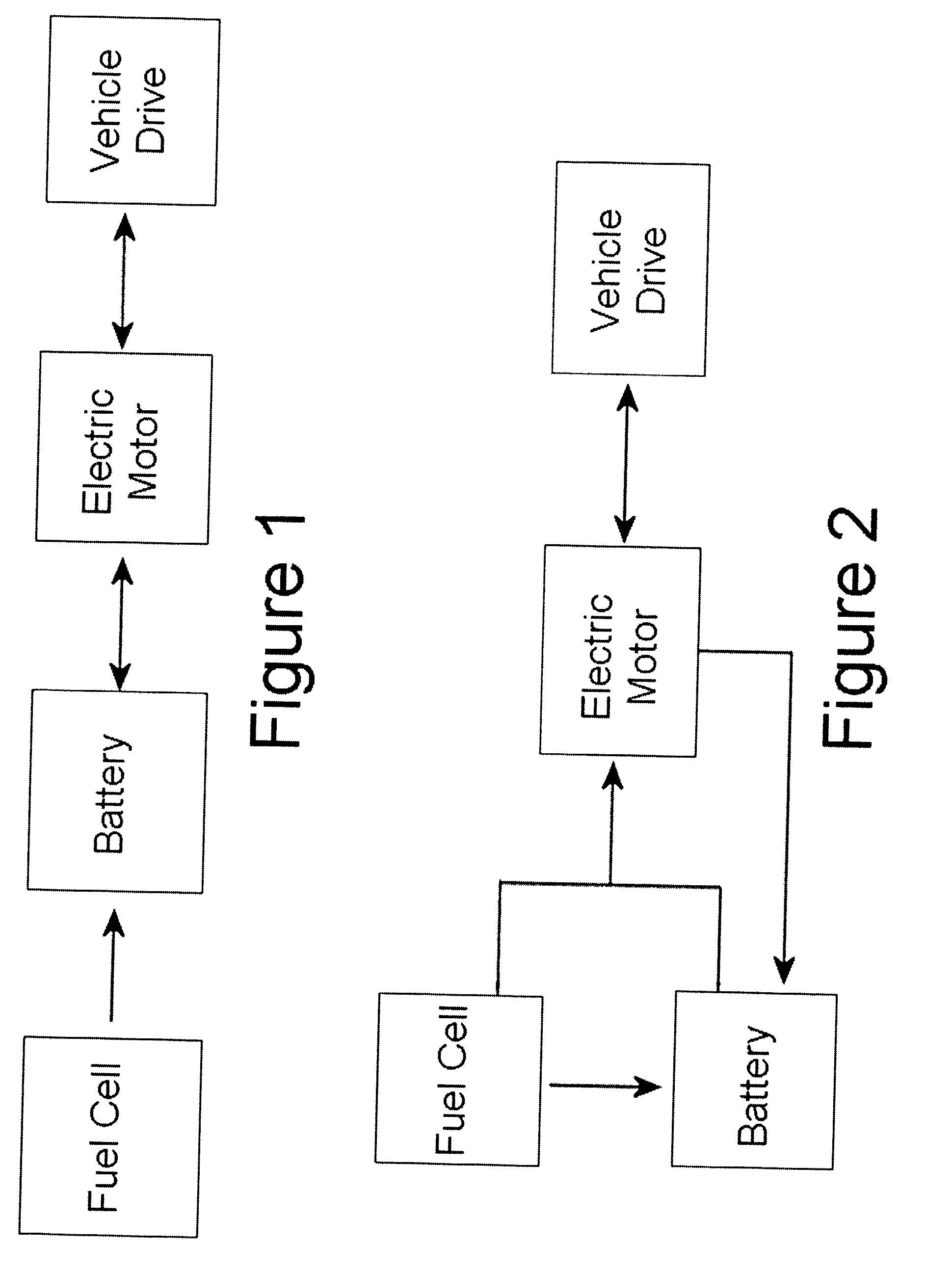
[0026]The present invention provides a hybrid vehicle powered by both a fuel cell and a battery working in conjunction with each other. Such a system may allow extended range and an increased amount of power on demand for the vehicle. Unlike previous hybrid vehicles utilizing gasoline fueled internal combustion engines, the present invention provides power to a vehicle without producing harmful pollutants. The disclosed fuel cell used in conjunction with high powered Nickel Metal Hydride batteries thereby provides a clean alternative to powering vehicles, bringing the world one step closer to a “Hydrogen Based Ecosystem”.
[0027]In one embodiment of the present invention there is provided a propulsion system for a hybrid vehicle comprising an integrated propulsion system including an alkaline fuel cell, a metal hydride hydrogen storage unit, an electric motor, a high specific power, high energy density nickel-metal hydride (NiMH) battery, and optionally a regenerative braking system. The NiMH batteries preferably have high peak power combined with high energy density and high cycle life at low depths of discharge.
[0028]In another embodiment of the present invention there is provided a power system for a hybrid vehicle comprising a NiMH battery module having high power combined with high energy density, high cycle life, good thermal management, and excellent gas recombination.

Problems solved by technology

As the world's population expands and its economy increases, the atmospheric concentrations of carbon dioxide are warming the earth causing climate change.
However, the global energy system is moving steadily away from the carbon-rich fuels whose combustion produces the harmful gas.
Furthermore, fossil fuels generate many other pollutants and are a causative factor in many strategic military struggles between nations.
As noted in recent newspaper articles, large industries, especially in America, have long been suspicious of claims that the globe is warming and have vociferously negated the science of climate change.
While the world's oil reserves are depletable, the supply of hydrogen remains virtually unlimited.
Furthermore, hydrogen, although presently more expensive than petroleum, is an inherently low cost fuel.
While hydrogen has wide potential application as a fuel, a major drawback in its utilization, especially in mobile uses such as the powering of vehicles, has been the lack of acceptable lightweight storage medium.
Storage of hydrogen as a compressed gas or liquid involves the use of large and heavy vessels, making the use of hydrogen to power vehicles less feasible.
Despite their seeming simplicity, many problems have prevented the widespread usage of fuel cells.
The P.E.M. fuel cell suffers from relatively low conversion efficiency and has many other disadvantages.
Unfortunately, not only are the noble metals costly, they are also susceptible to poisoning by many gases, and specifically carbon monoxide (CO).
Also, because of the acidic nature of the P.E.M fuel cell, the remainder of the materials of construction of the fuel cell need to be compatible with such an environment, which again adds to the cost thereof.
The proton exchange membrane itself is quite expensive, and because of its low conductivity, inherently limits the power performance and operational temperature range of the P.E.M. fuel cell (the PEM is nearly non-functional at low temperatures, unlike the fuel cell of the instant invention).
Also, the membrane is sensitive to high temperatures, and begins to soften at 120° C. The membrane's conductivity depends on water and dries out at higher temperatures, thus causing cell failure.
Therefore, there are many disadvantages to the P.E.M. fuel cell which make it somewhat undesirable for commercial / consumer use.
Unfortunately, conventional alkaline fuel cells still suffer from certain disadvantages.
For instance, conventional alkaline fuel cells still use expensive noble metals catalysts in both electrodes, which, as in the P.E.M. fuel cell, are susceptible to gaseous contaminant poisoning.
While the conventional alkaline fuel cell is less sensitive to temperature than the PEM fuel cell, the active materials of conventional alkaline fuel cell electrodes become very inefficient at low temperatures.

Method used


Image

  • Very low emission hybrid electric vehicle incorporating an integrated propulsion system including a fuel cell and a high power nickel metal hydride battery pack
  • Very low emission hybrid electric vehicle incorporating an integrated propulsion system including a fuel cell and a high power nickel metal hydride battery pack
  • Very low emission hybrid electric vehicle incorporating an integrated propulsion system including a fuel cell and a high power nickel metal hydride battery pack

Examples


example 1

[0201]Cells embodying those of the present HEV prototype system were constructed and tested. These cells and the HEV optimized prototype are described in Table 1 below.

[0202]

TABLE 1HEV OptimizedComparisonHEV PrototypePrototypepower density130016002700(W / L)specific power 600 6001000(W / kg)energy density 120 190 160(Wh / L)specific energy 55 70 60(Wh / kg)negativepastedCu substrateCu substrate,electrodethin electrodesconstructionnegative currentnickelcoppercoppercollectornegative alloymisch metalV18Ti15Zr18Ni29Cr5Co7Mn8V18Ti15Zr18Ni29Cr5Co7Mn8compositionpositivepastedpasted γ-phasepasted γ-phaseelectrodeNi (OH)2Ni (OH)2Ni (OH)2 withthinthickconductiveadditivesthinseparatorpolypropylenepolypropylenepolypropylenethinthinthincaseplasticstainless steelstainless steelaspect ratiosquaresquaresquaretopplasticstainless steelstainless steeltabsthickthick / laserthick / laserweldedwelded

[0203]As can be seen from Table 1, the embodiments of the invention, the HEV prototype cells and HEV optimized prototy...

example 2

[0205]The impact of the thermally conductive electrodes of the present invention can be evaluated independently. Comparison cells and thermally conductive cells were fabricated as described in Table 2.

[0206]

TABLE 2ThermallyComparison Cellconductive cellscapacity100 Ah100 Ahenergy density>>70 Wh / kg>>70 Wh / kgnegative electrodepastedsintered, compactedconstructionnegative alloymisch metalV18Ti15Zr18Ni29Cr5Co7Mn8compositionpositive electrodeNi (OH)2 pastedNi (OH)2 pasted ontoontofoam substratefoam substratecaseplasticstainless steeltopplasticstainless steeltemperature after80° C.34° C.charge / dischargecycling at C / 10overcharge to 120%of capacity

example 3

[0207]Cells (1-7 in Table 3, below) were fabricated as described in U.S. Pat. No. 5,330,861 using a high loft polypropylene separator and negative electrode alloy having the following composition:

V18Ti15Zr18Ni29Cr5Co7Mn8

except that the separators were sprayed with 1% aqueous solutions of PTFE on the side facing the negative electrode prior to assembling the cell. The control cells (designated C1-C7 in Table 3, below) were assembled using untreated separators.

[0208]These cells were charged and discharged at the indicated temperatures. The cells having the 1% PTFE coating on the surface of the separator demonstrated a consistent pressure reduction. As can be seen, this effect is even more pronounced at elevated temperatures and represents a significant improvement over the prior art. Table 3 also shows that cells of the present invention suffer no tradeoffs in terms of capacity.

[0209]

TABLE 3OverchargeTemperaturePressureCapacity(° C.)(psi)(Ah)ControlcellsC10324.77C210394.58C320894.46C...


PUM

PropertyMeasurementUnit
particle sizeaaaaaaaaaa
temperaturesaaaaaaaaaa

Abstract

A very low emission hybrid electric vehicle incorporating an integrated propulsion system which includes a fuel cell, a metal hydride hydrogen storage unit, an electric motor, high specific power, high energy density nickel-metal hydride (NiMH) batteries, and preferably a regenerative braking system. The nickel-metal hydride battery module preferably has a peak power density in relation to energy density as defined by:P>1,375−15E,where P is greater than 600 Watts / kilogram, where P is the peak power density as measured in Watts / kilogram and E is the energy density as measured in Watt-hours / kilogram.

Description

CROSS REFERENCE TO RELATED APPLICATIONS[0001]The present invention is a continuation-in-part of, and is entitled to the benefit of the earlier filing date and priority of, U.S. patent application Ser. No. 09 / 687,717, entitled “Catalytic Hydrogen Storage Composite Material And Fuel Cell Employing Same”, filed Oct. 13, 2000, now U.S. Pat. No. 6,492,056 which is assigned to the same assignee as the current application, the disclosure of which is hereby incorporated by reference.FIELD OF THE INVENTION[0002]The present invention relates generally to a very low emission hybrid electric vehicles incorporating an integrated propulsion system. More specifically, the present invention relates to hybrid electric vehicles with utilizing a fuel cell and battery.BACKGROUND OF THE INVENTION[0003]As the world's population expands and its economy increases, the atmospheric concentrations of carbon dioxide are warming the earth causing climate change. However, the global energy system is moving stead...

Claims


Application Information

Patent Timeline
Patent Type & Authority Patents(United States)
IPC IPC(8): H01M12/00H01M10/46H01M10/50H01M16/00H01M2/16H01M4/58H01M4/90C22C14/00B60L11/18C01B3/00C01B6/24C01B13/02C22C19/00H01M4/86H01M4/88H01M8/02H01M8/04H01M8/06H01M8/08H01M8/18
CPCB60L11/1898C01B3/0031C01B13/02H01M4/86H01M4/8615H01M4/90H01M4/9041H01M8/04291H01M8/065H01M8/08H01M8/184H01M8/186H01M8/04223H01M8/0668H01M8/083H01M2004/8684H01M2004/8689Y02E60/327Y02E60/528Y10S420/90Y02T10/7016Y02T90/34B60L50/72H01M8/04225Y02E60/32Y02E60/50Y02T90/40H01M8/0267Y02T10/70
Inventor OVSHINSKY, STANFORD R.STEMPEL, ROBERT C.
Owner CHEVRON TECH VENTURES
Why Eureka
Try Eureka