
Method of manufacturing a mask blank and a mask, the mask blank and the mask, and useless film removing method and apparatus

Inactive Publication Date: 2007-06-05
HOYA CORP
View PDF23 Cites 6 Cited by
  • Summary
  • Abstract
  • Description
  • Claims
  • Application Information

AI Technical Summary

Benefits of technology

[0015]It is an object of this invention to provide a mask blank which can suppress occurrence of dust resulting from separation of a resist film on a substrate peripheral portion and which desirably forms a removed area suitable for supplementary patterns along a peripheral or circumferential portion.
[0016]It is another object of this invention to provide a mask blank which can suppress occurrence of dust resulting from separation of a resist film on a substrate peripheral portion and which has a removed area of the resist film formed along a circumferential or peripheral area corresponding to a substrate support member of an exposure device.

Problems solved by technology

Such a hump at the peripheral portion gives rise to the following problems when a resist is used as the coating liquid.
Peeled off resist acts as a dust source and adheres to the principal surface of the mask blank and, as a result, causes an undesired defect to occur on the mask blank.
As the substrate becomes large in size, its weight becomes heavy.
This impertinently heightens a possibility of occurrence of dust due to contacts between the peripheral portion of the substrate and a mask case, when the substrate with the resist film is introduced into the mask case.
The resist film is removed until an area of forming the supplementary patterns, which renders the supplementary patterns defective.
However, the resist film can not be removed in consideration of a configuration of the reticle chuck and accuracy of the position is inevitably deteriorated in the exposure device.
However, collation of the defect degree data becomes difficult once each mask blank is picked out of the mask case to be investigated and is placed into a different position of the mask case.
This is because using the same cover brings about undesirably removing the peripheral portions of the mask substrate to positions of forming the alignment marks.

Method used


Image

  • Method of manufacturing a mask blank and a mask, the mask blank and the mask, and useless film removing method and apparatus
  • Method of manufacturing a mask blank and a mask, the mask blank and the mask, and useless film removing method and apparatus
  • Method of manufacturing a mask blank and a mask, the mask blank and the mask, and useless film removing method and apparatus

Examples


Embodiment Construction

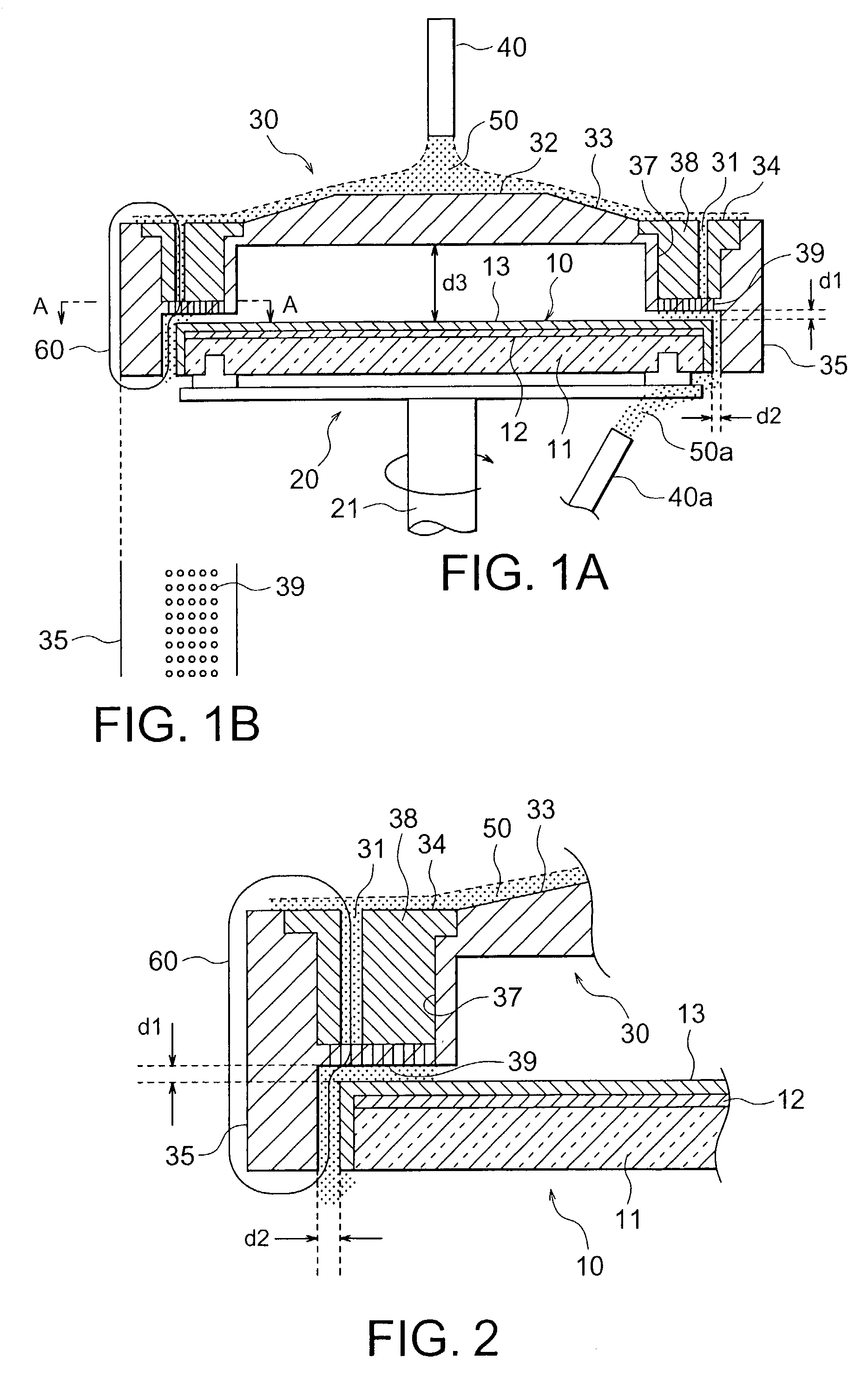
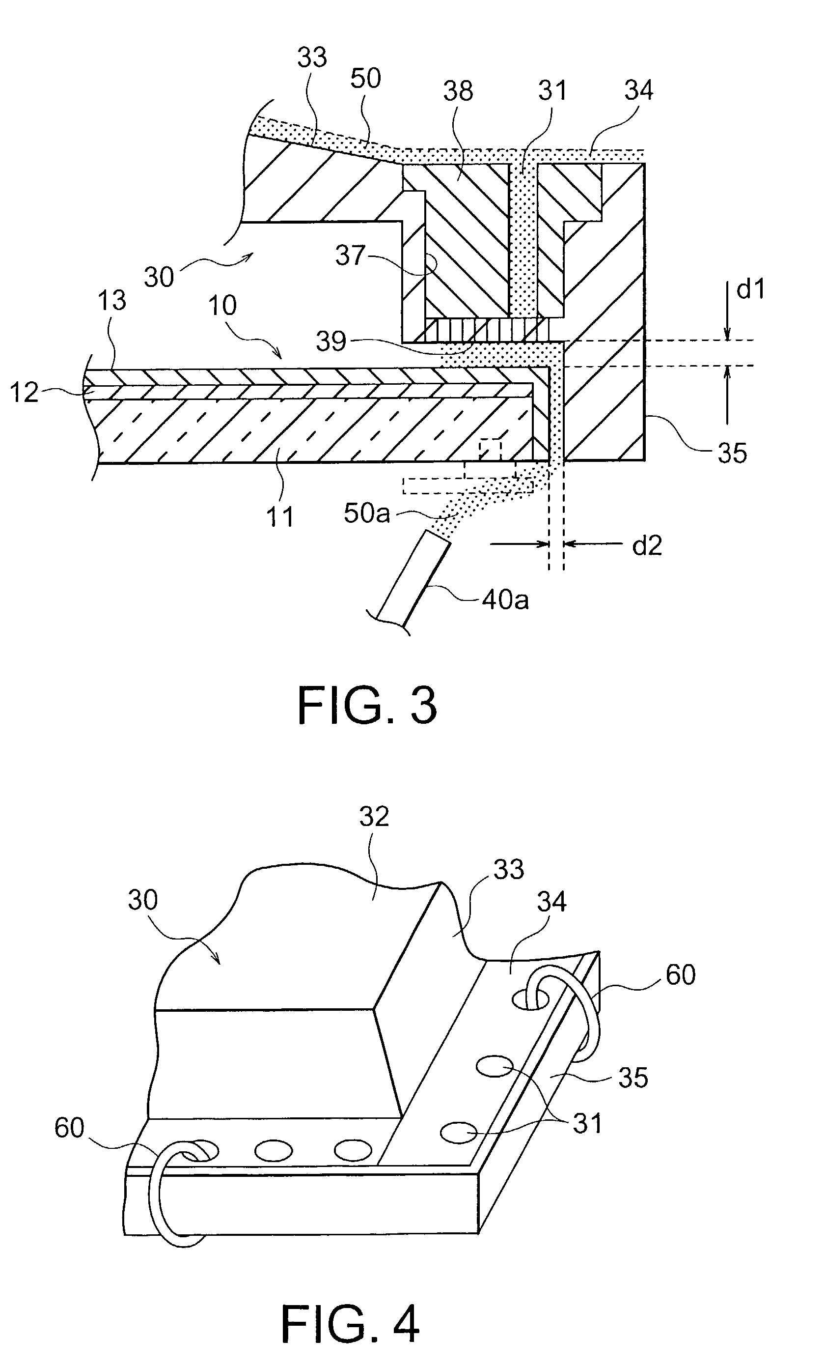
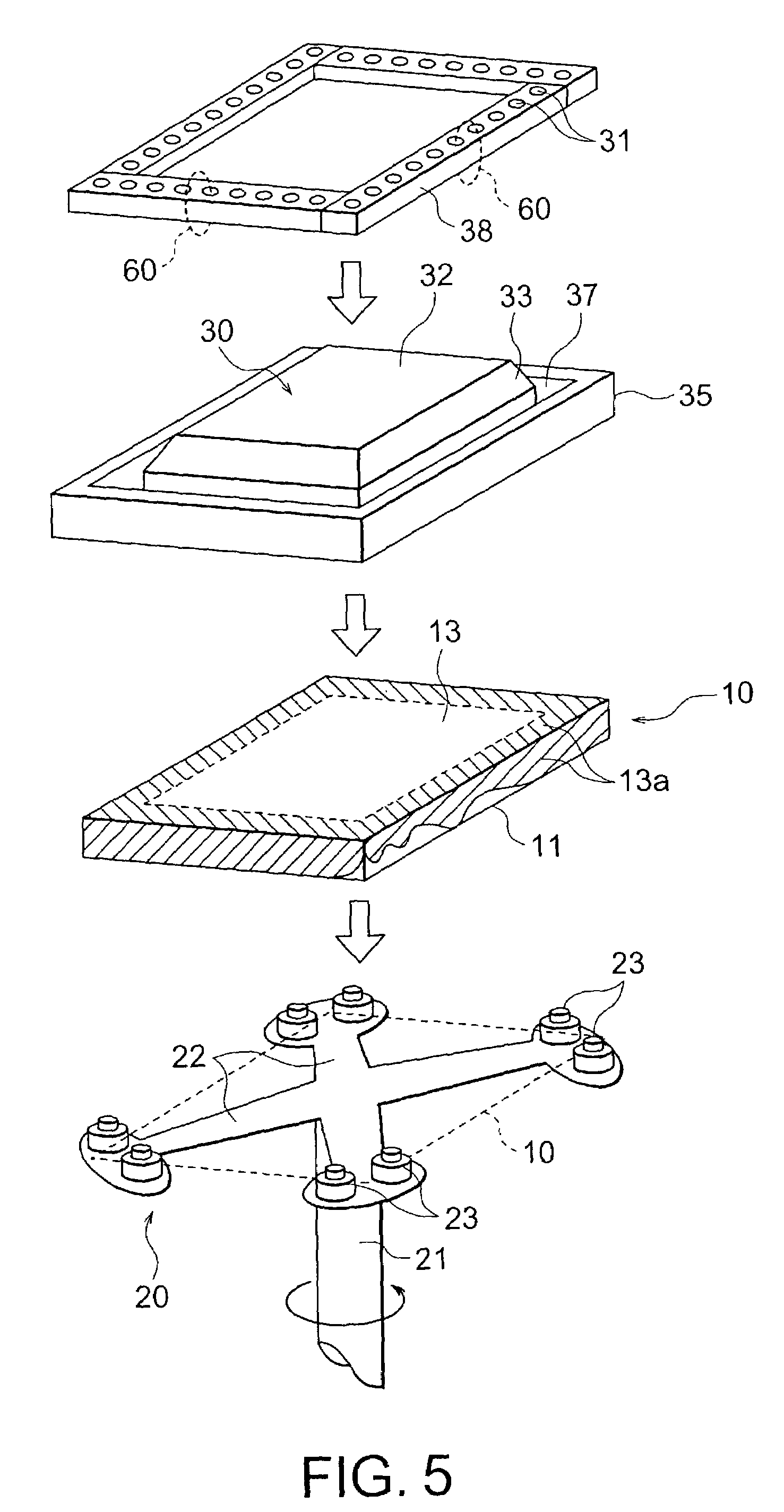
[0098]Referring to FIGS. 1A through 5, description will be made about a useless film removing apparatus and method according to an embodiment of this invention. In the illustrated example, description will be also made about a method of manufacturing a mask blank, especially, a photo-mask blank, which is also related to this invention. In the following, description will be at first directed to the photo-mask blank and then to the useless film removing apparatus, and thereafter to the method of manufacturing the photo-mask blank together with the method of removing the useless film. Finally, description will be made about the photo-mask blank manufactured by the manufacturing method.

[0099]In FIGS. 1A through 5, a substrate 10 may be a photo-mask blank (FIGS. 2 and 3) which has a transparent base 11 of synthetic quartz glass on a front surface of the transparent base, a light shielding film 12 of chromium, and an unbaked resist film 13. Specifically, the transparent base 11 has a size...


PUM


Abstract

In a method of removing a useless film formed along a circumferential portion of a substrate, so as to provide a removed portion, a cover member is covered over the substrate to supply a solvent to the useless portion through solvent supply holes. The circumferential portion which has the removed portion and a non-removed portion serves to provide an identification code or the like for identifying the substrate. The solvent supply holes are formed in a solvent guide member which is exchangeably attached to a peripheral portion of the cover member. The substrate may be either a mask blank or a mask that has the identification pattern formed by removing the useless film by the above-mentioned method.

Description

BACKGROUND OF THE INVENTION[0001]This invention relates to a mask blank which is used in a lithography process on fabricating a semiconductor device or the like and a method of manufacturing the mask blank. In addition, this invention also relates to a method of removing a useless film partially left on a surface of a substrate, such as a semiconductor substrate, and a removing apparatus for carrying out the method. Although the term “useless” will be mainly used in the instant specification, the term “unnecessary” may be used instead of the term “useless”.[0002]In a field of manufacturing a semiconductor device, mask blank, and the like, it is often required to partially remove a useless portion from a film deposited on a principal surface of a substrate.[0003]For example, let consideration be made about coating a resist film or a spin on glass (SOG) film on the substrate by a spin coat method. In this event, the substrate that is substantially kept horizontal is rotated. Under the...

Claims


Application Information

Patent Timeline
IPC IPC(8): G03F1/00G03C5/00G03F7/16G03F7/20
CPCG03F1/14G03F7/168G03F7/2028G03F1/38G03F1/50
Inventor HATA, MITSUAKI
Owner HOYA CORP
Learn More