Safety interlock and protection circuit for permanent magnet motor drive

a protection circuit and permanent magnet technology, applied in the direction of motor/generator/converter stopper, dynamo-electric gear control, dynamo-electric converter control, etc., can solve the problems of affecting the safety of permanent magnet motors, and exhibiting two potentially dangerous conditions. , to achieve the effect of discharging excess kinetic energy stored in the spinning motor

Active Publication Date: 2007-06-05
INFINEON TECH AMERICAS CORP
View PDF6 Cites 15 Cited by
  • Summary
  • Abstract
  • Description
  • Claims
  • Application Information

AI Technical Summary

Benefits of technology

[0008]The present invention does not require any mechanical components for braking or additional power devices to remove and dissipate excess kinetic energy stored in the spinning motor. The present invention provides a simple circuit realized by single or multiple integrated circuits or by either discrete or monolithic components to achieve all of the above objects.
[0009]According to the invention, a circuit is provided for protecting against controller failure wherein the controller provides control signals for controlling a DC to AC inverter fed by a DC bus and driving a permanent magnet motor, the circuit comprising a first circuit for monitoring the DC bus voltage and, in the event the DC bus voltage exceeds a first threshold due to a counter EMF generated by the motor, for producing a signal to the controller to provide a switch state to the inverter whereby the counter EMF is dissipated substantially in a motor circuit resistance of the permanent magnet motor as a result of a short circuit condition provided by the switch state of the inverter, thereby preventing the DC bus voltage of the inverter from exceeding the first threshold and causing the permanent magnet motor speed to be reduced.

Problems solved by technology

While this mechanical solution is achievable, it is prohibitively expensive and complex and also is subject to mechanical failure.
In the event of a controller failure, a permanent magnet motor exhibits two potentially dangerous conditions.
In this condition, if the door or the lid of the washer is opened, it creates a safety hazard of bodily injury if a person physically attempts to access the spinning drum.
The other condition is that a permanent magnet motor may generate overvoltage on the DC bus when the controller disengages from energizing the motor as a result of controller failure.
If a failure occurs at this time, the voltage generated is quite high.
This will result in damaging the power devices and high voltage ICs in the system since they are normally rated at 600 volts for a 230 volt AC RMS main input.
The DC bus capacitor can also be damaged.
Once damage occurs in the power system, it may no longer be possible to provide a safety door lock / braking mechanism since any circuits on the board likely will be damaged as well or be inoperative.

Method used


Image

  • Safety interlock and protection circuit for permanent magnet motor drive
  • Safety interlock and protection circuit for permanent magnet motor drive
  • Safety interlock and protection circuit for permanent magnet motor drive

Examples


Embodiment Construction

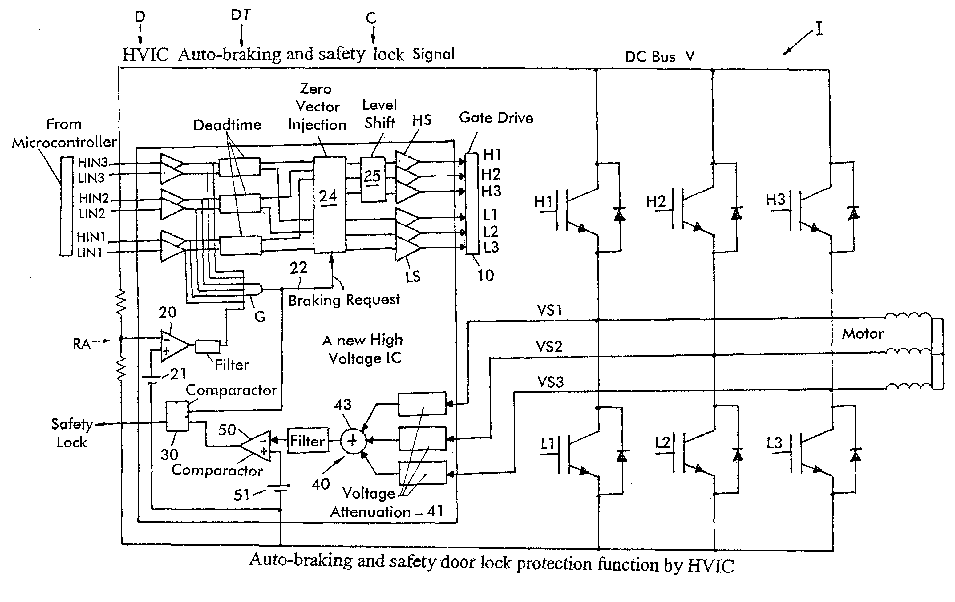
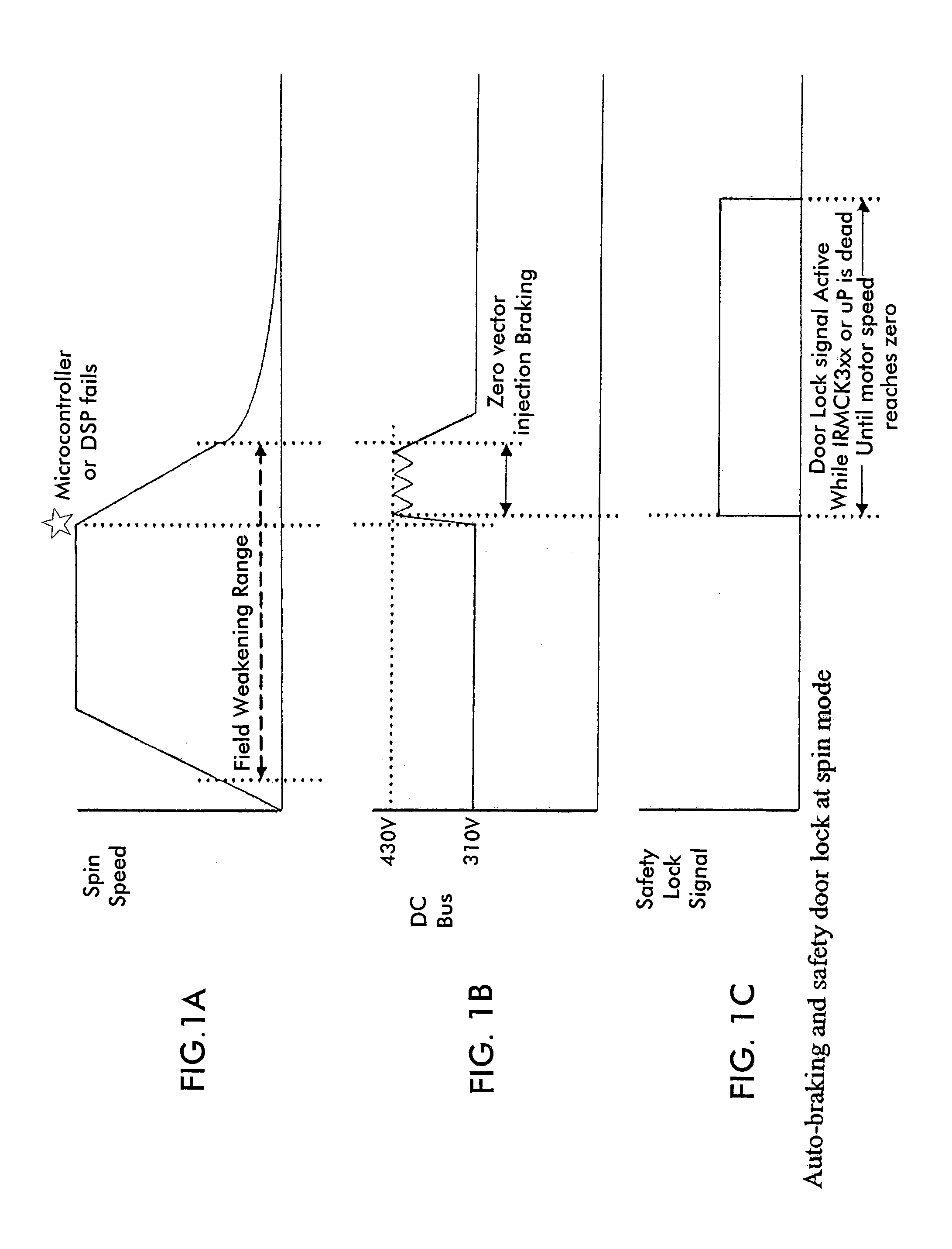
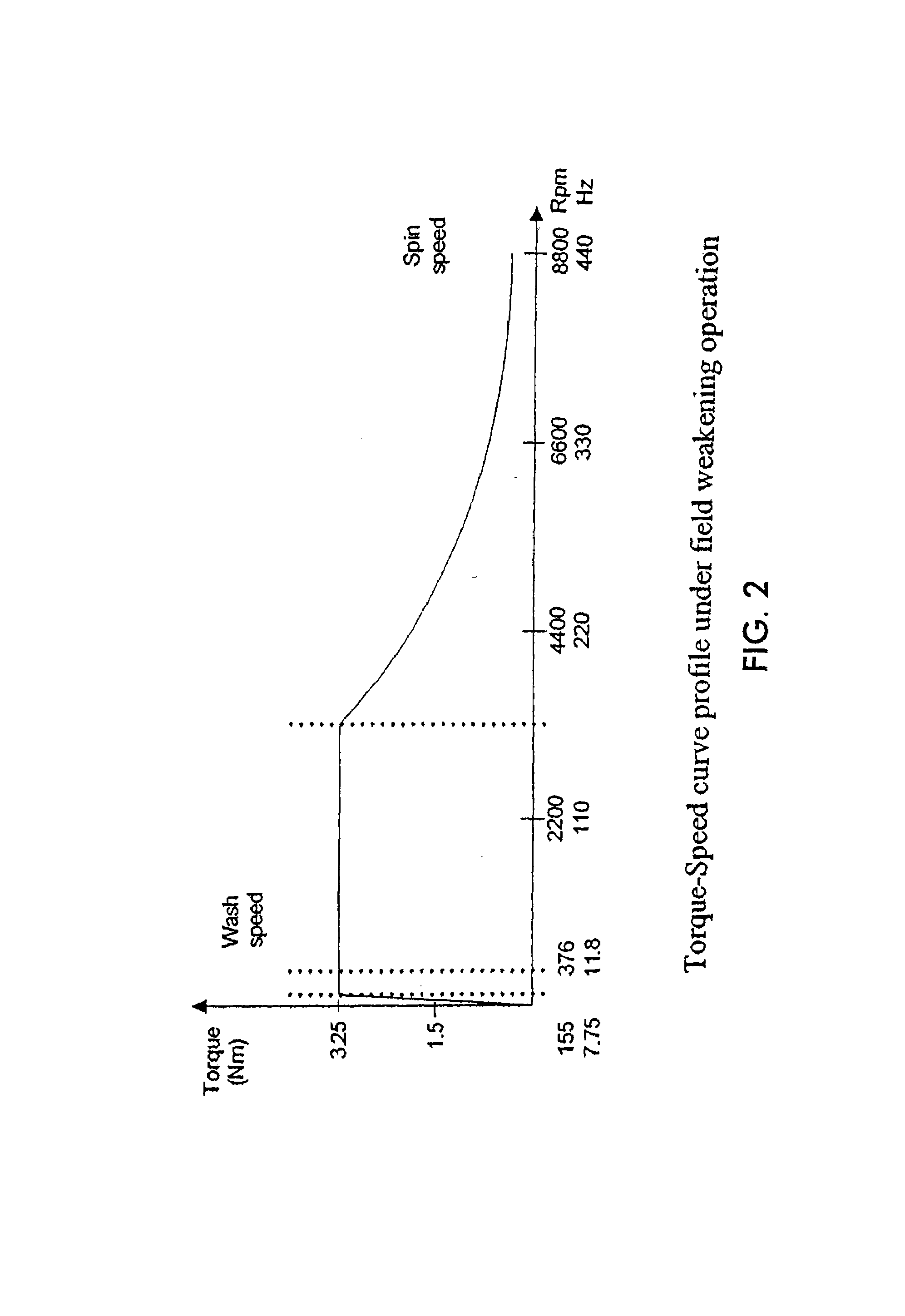
[0020]With reference now to the drawings, FIG. 1 shows the most hazardous state of conditions if the controller fails during a field weakening operation of the motor during the spin mode. The mode of operation as shown is at high speed spin mode with a deep field weakening operation of the permanent magnet motor. In the case shown, the controller is shown as failing at the very end of the spin mode when the speed is highest in the spin mode and in the deepest area of the field weakening operation. The failure is shown by the star in the top graph (FIG. 1A) of FIG. 1. FIG. 2 shows the motor torque-speed curve. From FIG. 2, the point of failure is near the end of the high speed spinning operation, in the example shown, near 8800 rpm.

[0021]FIG. 3 shows a portion of a controller C circuit driving the inverter I, which inverter comprises three half bridges comprised of IGBTs, as well known. The control signals to the controller C are provided by a microprocessor or DSP, not shown, provid...


PUM


Abstract

A circuit for protecting against controller failure wherein the controller provides control signals for controlling a DC to AC inverter fed by a DC bus and driving a permanent magnet motor, the circuit comprising a first circuit for monitoring the DC bus voltage and, in the event the DC bus voltage exceeds a first threshold due to a counter EMF generated by the motor, for producing a signal to the controller to provide a switch state to the inverter whereby the counter EMF is dissipated substantially in a motor circuit resistance of the permanent magnet motor as a result of a short circuit condition provided by the switch state of the inverter, thereby preventing the DC bus voltage of the inverter from exceeding the first threshold and causing the permanent magnet motor speed to be reduced.

Description

CROSS-REFERENCE TO RELATED APPLICATION[0001]The present application claims the priority and benefit of U.S. Provisional Application Ser. No. 60 / 652,861 filed Feb. 14, 2005 entitled SAFETY DOOR LOCK AND PROTECTION CIRCUIT FOR PM MOTOR BASED WASHER APPLICATION, the entire contents of which are hereby incorporated by reference.BACKGROUND OF THE INVENTION[0002]The present invention relates to a safety interlock and protection circuit used in a DC-AC inverter motor controller driving a permanent magnet motor, for example, driving the drum of a washing machine. The circuit according to the invention performs a door lock function and provides overvoltage protection and motor braking when the main motor controller fails and loses control while the permanent magnet motor is still spinning.[0003]A permanent magnet motor has higher power density and higher torque per ampere than an induction motor. Induction motors have been commonly used in the past in washing machine applications. Permanent ...

Claims


Application Information

Patent Timeline
Patent Type & Authority Patents(United States)
IPC IPC(8): H02P3/00
CPCD06F37/42H02P25/021H02P29/021H02P25/024H02P29/0241D06F34/10
Inventor GALLI, GIOVANNITAKAHASHI, TOSHIO
Owner INFINEON TECH AMERICAS CORP
Why Eureka
Try Eureka