Optical film and liquid-crystal display device

a liquid crystal display device and optical film technology, applied in the direction of lighting and heating apparatus, instruments, polarising elements, etc., can solve the problems of difficult to reduce the thickness, size and weight of a transmission the volume and weight of the liquid crystal display device is large, and the liquid crystal display device substantially hardly functions as a reflection type liquid crystal display device, etc., to achieve the effect of ensuring efficient entrance, reflection and transmission of external light, and avoiding the effect o

Inactive Publication Date: 2007-06-05
NITTO DENKO CORP
View PDF49 Cites 12 Cited by
  • Summary
  • Abstract
  • Description
  • Claims
  • Application Information

AI Technical Summary

Benefits of technology

[0008]An object of the present invention is to develop an optical film by which the optical path of the light incident on one of side surfaces of a liquid-crystal display device is changed to a viewing direction efficiently, and with which it is possible to form a transmission type or reflection-transmission double type liquid-crystal display device which is small in thickness, which is light in weight, and display of which is bright and easy to view.
[0012]The optical film according to the present invention is disposed along the viewing surface of a liquid-crystal display panel having an illuminator on one of side surfaces of the panel. Hence, the optical path of the light incident on the side surface or the transmission light of the incident light is changed efficiently to the viewing direction of the liquid-crystal display panel by optical path changing slopes disposed on the optical film. Hence, the light can be utilized for liquid-crystal display in a transmission mode. Hence, it is possible to form a transmission type liquid-crystal display device which is small in thickness and light in weight, which is excellent in brightness and uniformity of brightness, which is low in display unevenness and which is excellent in display quality. Moreover, because flat surface portions are disposed between the optical path changing slopes in the optical film, external light can be made to enter efficiently through the flat surface portions. Hence, when the entering external light is reflected by the reflection layer, the external light can be utilized for liquid-crystal display in a reflection mode. A reflection mode system can be formed as well as the aforementioned transmission mode system. Hence, it is possible to form a transmission-reflection double type liquid-crystal display device which is small in thickness and light in weight, which is excellent in brightness and uniformity of brightness, which is low in display unevenness and which is excellent in display quality.
[0013]The aforementioned effect is produced by an optical path control type optical film which mainly uses slope reflection to control the optical path of light. That is, the light incident on one of side surfaces of the liquid-crystal display panel or the transmission light of the incident light is reflected by optical path changing slopes so that the optical path of the light can be changed with good directivity. Hence, good visibility in a transmission mode can be achieved. Moreover, flat surfaces can be disposed easily between the optical path changing slopes. Hence, external light is transmitted through the flat surfaces so that entering of external light can be ensured sufficient. Hence, good visibility in a reflection mode can be also achieved. In a method of scatter reflection by a roughened surface of a scattering sheet 6 shown in FIG. 14, or the like, it is difficult to achieve the aforementioned effect. Incidentally, JP-A-5-158033 discloses a reflection type liquid-crystal display device in which illumination light is made incident on one of side surfaces of a liquid-crystal display panel and totally reflected by a visual side cell substrate and in which the reflected light is scattered by a roughened surface type reflector so that the scattered light is utilized for display.
[0015]On the other hand, according to the present invention, the optical path control type optical film, which uses slope reflection to control the optical path of light, mainly utilizes light exhibiting a peak in a direction of regular reflection and controls the optical path of the reflected light. Hence, directivity, especially frontal directivity, favorable for display can be provided easily. Hence, a bright transmission mode can be achieved. Also in a reflection mode, flat portions of the optical film except the optical path changing slopes can be utilized, and efficient entrance, reflection and transmission of external light can be ensured. Hence, the state of light can be balanced easily so as to be favorable to both reflection and transmission modes. Further, according to the present invention, the optical film is designed to be able to be bonded to a glass substrate, or the like, of a liquid-crystal cell through adhesive means having a large refractive index. Hence, as indicated by the arrows in FIG. 7, the total reflection on the bonding interfaces can be reduced in the optical film to thereby make it possible to form a transmission type or reflection-transmission double type liquid-crystal display device which is excellent in brightness and uniformity of brightness, which is low in display unevenness and which is excellent in display quality. If the total reflection were great in the optical film, the quantity of light which is incident on one of side surfaces of the cell and which is transmitted through the cell from the side surface so as to enter the optical film would be reduced. Particularly, transmission light which is more approximately parallel with the cell substrate as indicated by the arrow in FIG. 10 would cause total reflection more easily. That is, light which is transmitted to a position farther from the incidence side surface would cause total reflection more easily. As a result, brightness in a position far from the incidence side surface would be reduced to increase variation in brightness. Hence, display quality of the display device would be lowered.

Problems solved by technology

In the meanwhile, it is difficult to reduce thickness, size and weight of a transmission type liquid-crystal display device provided with a back-lighting system using a background-art bottom type or side-lighting type light pipe.
If there is no half-transmission type reflector, viewing in a reflection mode by using external light is so dark that the liquid-crystal display device substantially hardly functions as a reflection type liquid-crystal display device.
The addition of the half-transmission type reflector, however, makes the volume and weight of the liquid-crystal display device larger.
There is therefore a problem that not only viewing in a transmission mode but also viewing in a reflection mode becomes dark so that brightness in a reflection mode is inferior to that of a reflection exclusive type liquid-crystal display device using a high-reflectance reflection layer.

Method used


Image

  • Optical film and liquid-crystal display device
  • Optical film and liquid-crystal display device
  • Optical film and liquid-crystal display device

Examples


example 1

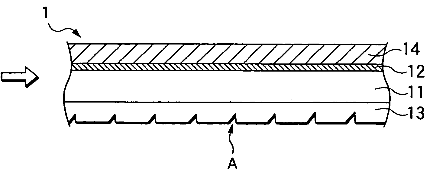
[0094]A mold processed into a predetermined shape in advance was filled with acrylic ultraviolet-curable resin (ARONIX UV-3701, made by TOAGOSEI Co., Ltd.) by dropping with a dropper. An 80 μm-thick triacetylcellulose (TAC) film (having a saponified surface) was disposed quietly on the resin, and made to adhere closely to the resin by a rubber roller so as to eliminate excessive resin and bubbles. The TAC film with the resin was irradiated with ultraviolet rays by a metal halide lamp so as to be cured. The resin-including TAC film cured thus was stripped off from the mold and cut into a predetermined size. Thus, a transparent film was obtained so that a layer of a plurality of optical path changing means having a refractive index of 1.533 was formed on the TAC film having a refractive index of 1.49. Then, a tacky layer with a refractive index of 1.47 was provided on the other surface of the transparent film on which the plurality of optical path changing means were not formed. Thus,...

example 2

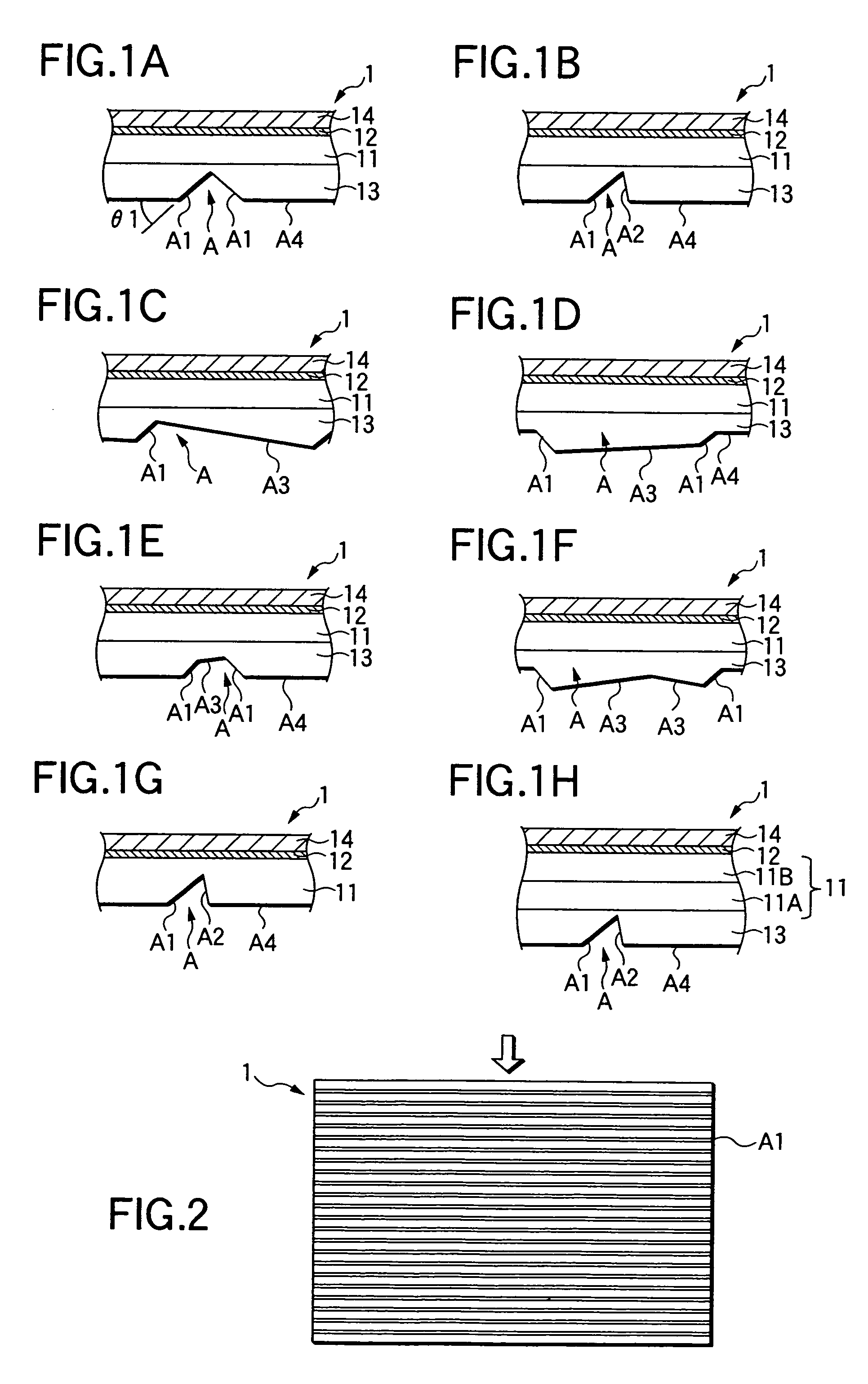
[0097]A transmission type liquid-crystal display device was obtained by using an optical film in the manner similar to that in Example 1, except that the optical film was formed to have a plurality of optical path changing means (FIG. 1B) each of which had an optical path changing slope A1 inclined at an angle of about 42 degrees, a steep slope A2 having a vertex angle of 70 degrees with the optical path changing slope A1, and a flat surface A4 having a projected area not smaller than 10 times as large as the total projected area of the optical path changing slope A1 and the steep slope A2 on the film plane.

example 3

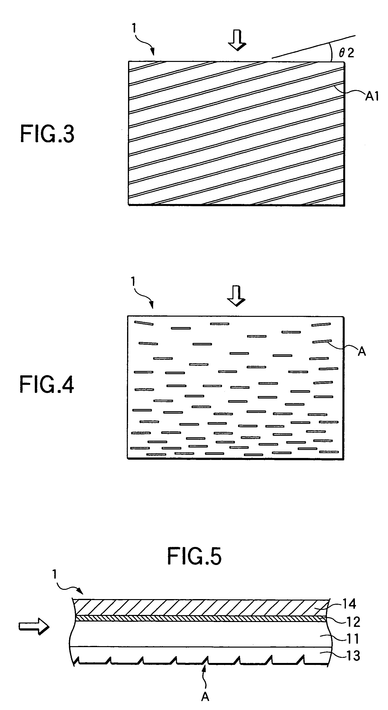
[0098]A transmission type liquid-crystal display device was obtained by using an optical film (FIG. 6) in the manner similar to that in Example 1, except that the optical film was formed to have a plurality of optical path changing means each having a length of 80 μm (FIG. 1B). Each of the plurality of optical path changing means had an optical path changing slope A1 which had an inclination angle of about 42 degrees and which had a projected width of 10 μm on the film plane, and a steep slope A2 which had an inclination angle of about 55 degrees. The plurality of optical path changing means were disposed so that the lengths of the plurality of optical path changing means were substantially parallel with one another in the widthwise direction of the optical film, and so that the density of the optical path changing means became gradually higher as the location went farther from the side surface, on which the light is incident, in the widthwise direction of the optical film. Incident...


PUM

PropertyMeasurementUnit
thicknessaaaaaaaaaa
thicknessaaaaaaaaaa
refractive indexaaaaaaaaaa

Abstract

An optical film has a transparent film and an adhesive layer provided on one surface of the transparent film. The adhesive layer has a refractive index different by 0.12 or less from that of a layer of the one surface of the transparent film. The transparent film has an average in-plane retardation of not larger than 30 nm. A repetitive prismatic structure is provided on the other surface of the transparent film, the repetitive prismatic structure having optical path changing slopes aligned in a substantially constant direction at an inclination angle in a range from 35 to 48 degrees with respect to a plane of the transparent film.

Description

[0001]This is a divisional of application Ser. No. 09 / 758,165 filed Jan. 12, 2001, now U.S. Pat. No. 6,747,801, the disclosure of which is incorporated herein by reference.BACKGROUND OF THE INVENTION[0002]1. Field of the Invention[0003]The present invention relates to an optical film by which the optical path of the light incident on one of side surfaces of a liquid-crystal display device is changed to a viewing direction efficiently, and with which it is possible to form a transmission type or reflection-transmission double type liquid-crystal display device which is small in thickness, which is light in weight, which is excellent in brightness and uniformity of brightness and display of which is easy to view.[0004]The present application is based on Japanese Patent Applications No. 2000-4241, 2000-21309 and 2000-85718, which are incorporated herein by reference.[0005]2. Description of the Related Art[0006]Greater reduction in thickness, size and weight of transmission type liquid-...

Claims


Application Information

Patent Timeline
Patent Type & Authority Patents(United States)
IPC IPC(8): G02B27/28G02B5/04G02F1/13363F21V8/00G02B6/00
CPCG02B5/045G02B6/0053G02B6/0061G02B6/0036G02B6/0038G02F1/13363
Inventor UMEMOTO, SEIJIARIYOSHI, TOSHIHIKOSUZUKI, TAKAO
Owner NITTO DENKO CORP
Why Eureka
Try Eureka