Method for forming a resist pattern of magnetic device
a magnetic device and resist pattern technology, applied in nanoinformatics, instruments, record information storage, etc., can solve the problems of increasing the resistance of the magnetic head manufactured by the conventional manufacturing method, the inability to maintain good electrical contact between the upper electrode and the increase of the resistance of the lead layer and the non-magnetic metal layer. to achieve the effect of increasing the recording density
- Summary
- Abstract
- Description
- Claims
- Application Information
AI Technical Summary
Benefits of technology
Problems solved by technology
Method used
Image
Examples
first embodiment
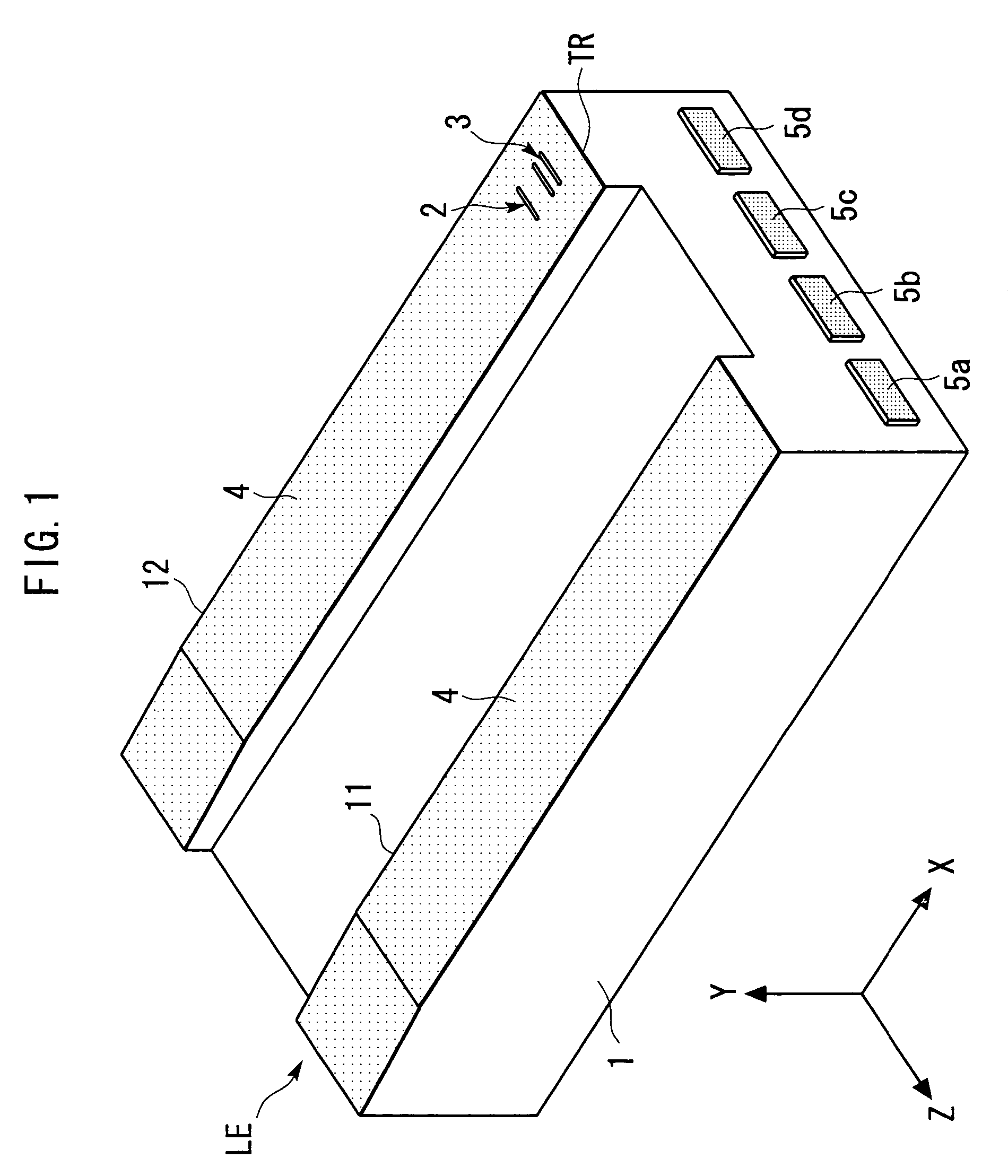
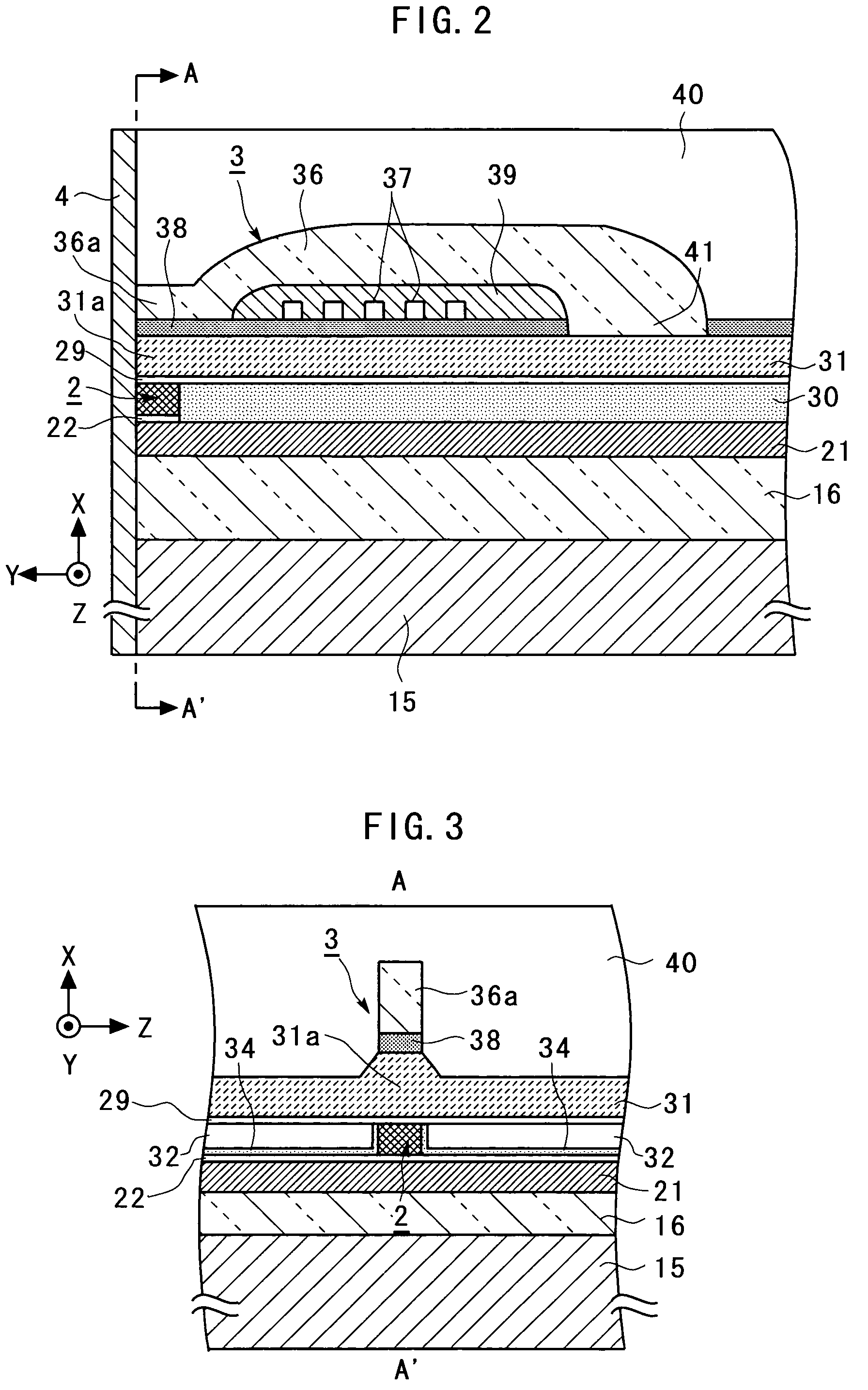
[0119]First, a magnetic head manufactured by a magnetic head manufacturing method according to the present invention will be described with reference to FIGS. 1 to 5.
[0120]FIG. 1 is a general perspective view schematically illustrating the magnetic head manufactured by the magnetic head manufacturing method according to the first embodiment of the present invention. FIG. 2 is an enlarged cross-sectional view schematically illustrating a portion of a TMR device 2 and an inductive magnetic transducing device 3 in the magnetic head illustrated in FIG. 1. FIG. 3 is a general sectional view taken along a line A–A′ indicated by arrows in FIG. 2. FIG. 4 is a further enlarged view illustrating around the TMR device 2 in FIG. 2. FIG. 5 is a further enlarged view around the TMR device 2 in FIG. 3. For facilitating the understanding, an X-axis, a Y-axis and a Z-axis, orthogonal to one another, are defined as shown in FIGS. 1 to 5 (the same applies to figures later described). The Z-axis direct...
second embodiment
[0170]Next, a magnetic head manufacturing method according to the present invention will be described with reference to FIGS. 25 to 27.
[0171]FIG. 25 is an enlarged cross-sectional view schematically illustrating a portion of a TMR device 2 and an inductive magnetic transducing device 3 in a magnetic head manufactured by the magnetic head manufacturing method according to the second embodiment of the present invention. FIG. 26 is a further enlarged view around the TMR device 2 in FIG. 25. FIGS. 25 and 26 correspond to FIGS. 2 and 4, respectively. FIG. 27 is a cross-sectional view schematically illustrating a step in the magnetic head manufacturing method according to the second embodiment of the present invention, and corresponds to FIG. 17. In FIGS. 25 to 27, elements identical or corresponding to those of FIGS. 1 to 5 and FIG. 17 are designated by the same reference numerals, and repeated description thereon is omitted.
[0172]The, magnetic head illustrated in FIGS. 25 and 26 differs...
third embodiment
[0177]Next, a magnetic head manufacturing method according to the present invention will be described with reference to FIGS. 28 to 30.
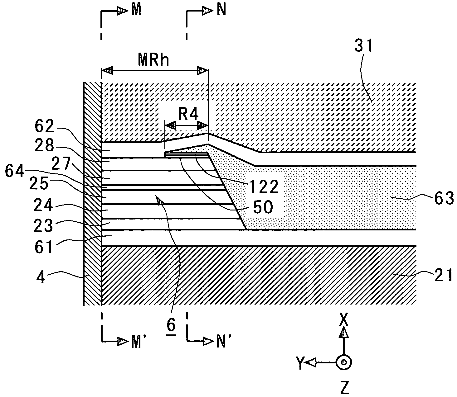
[0178]FIG. 28 is an enlarged cross-sectional view schematically illustrating a portion of a GMR device 6 and an inductive magnetic transducing device 3 in a magnetic head manufactured by the magnetic head manufacturing method according to the third embodiment of the present invention. FIG. 29 is a further enlarged view around the GMR device 6 in FIG. 28. FIG. 30 is a general sectional view taken along a line B–B′ indicated by arrows in FIG. 29. FIGS. 28 to 30 correspond to FIGS. 2, 4 and 5, respectively. In FIGS. 28 to 30, elements identical or corresponding to those of FIGS. 1 to 5 are designated by the same reference numerals, and repeated description thereon is omitted.
[0179]The magnetic head illustrated in FIGS. 28 to 30 is an example of a magnetic head having the LOL structure. The magnetic head illustrated in FIGS. 28 to 30 differs from the mag...
PUM
| Property | Measurement | Unit |
|---|---|---|
| Angle | aaaaa | aaaaa |
| Angle | aaaaa | aaaaa |
| Shape | aaaaa | aaaaa |
Abstract
Description
Claims
Application Information
 - R&D
- Intellectual Property
- Life Sciences
- Materials
- Tech Scout
- Unparalleled Data Quality
- Higher Quality Content
- 60% Fewer Hallucinations
Browse by: Latest US Patents, China's latest patents, Technical Efficacy Thesaurus, Application Domain, Technology Topic, Popular Technical Reports.
© 2025 PatSnap. All rights reserved.Legal|Privacy policy|Modern Slavery Act Transparency Statement|Sitemap|About US| Contact US: help@patsnap.com


