Method for preparing composite flexible graphite material

a graphite material and flexible technology, applied in the field of materials, can solve the problems of less than ideal compromise on key structural and performance criteria, reduce the effectiveness of articles per unit cost and per unit weight, and increase the cost of articles being produced, so as to reduce the level of voids in sheets, improve product performance, and reduce electrical and thermal resistance

Inactive Publication Date: 2007-06-19
GRAFTECH INT HLDG INC
View PDF14 Cites 42 Cited by
  • Summary
  • Abstract
  • Description
  • Claims
  • Application Information

AI Technical Summary

Benefits of technology

[0067]It is an advantage of the invention that layers or other zones, e.g., partial layers such as precut inserts, can have void conditions differing in adjacent zones. By void condition is meant the percentage of the sheet represented by voids, which are generally found in the form of entrapped air. Generally, this is accomplished by the application of pressure to the sheet (which also has the effect of densifying the sheet) so as to reduce the level of voids in the sheet, for instance in a calender mill or platen press. Advantageously, the flexible graphite sheet is densified to a density of at least about 1.3 g / cc (although the presence of resin in the system can be used to reduce the voids without requiring densification to so high a level).
[0069]The invention provides a material useful as a substrate for an embossed flexible graphite sheet and comprises a composite flexible graphite sheet comprising a plurality of zones (e.g., layers or partial layers) of resin-impregnated, flexible graphite sheet. At least one of the plurality of zones has a characteristic different than at least one other of said plurality of zones. Among the various characteristics that are advantageously varied between zones according to the invention are all of those above or as may otherwise be measured and can be related to properties of a final shaped article or an effect on the process for making it. Typically, the invention can provide useful properties in the characteristics of final shaped articles when the difference in the characteristics referred to is greater than about 5%, and more typically from about 10% up to about 200%, based on the smaller of the two values. In many cases, differences of from about 20 to about 75% on this basis are valuable. In others difference values up to as much as 500% can have a particular utility.
[0070]In one form, the composite material of the invention will be provided with a unique combination of properties by further including a layer of a diverse material interposed between at least two layers of said plurality of layers. The diverse material can be a foraminous material, e.g., selected for any of a variety of added advantages and is typically one selected from the group consisting of perforated films and foils, and woven and nonwoven fabrics and webs of plastic, metal and / or natural composition. In all cases, the materials are employed to provide a unique ability to control final shaped article characteristics, e.g., density and surface properties, by preselecting layers of different characteristic, e.g., density or void condition, to comprise the layers of the composite. In other cases, the diverse material can be a nonporous film, sheet or foil of plastic or metal to aid in sealing and for other useful properties. By properly utilizing suitable inter layers with impregnated materials, an external binder can be eliminated, further decreasing electrical and thermal resistance.
[0071]Referring again to FIG. 1, a composite material 10 of the invention, is shown schematically, and is of type useful for a number of purposes including as a substrates for forming embossed flexible graphite articles. The composite is made of a plurality of layers, here two layers, 12 and 14. However, the number of layers is not limited to two, and up to ten or more layers can be employed to advantage. Indeed, an important aspect of the invention is the opportunity to improve the product through the reduction of variation in area weight. When randomly selected the variation in a laminate will be reduced by the square root of the number of layers in the laminate, through deliberate selection, further improvements can be achieved. Impregnated and dried materials in a condition for embossing may be assembled to accumulate any desired target density. When then formed the assembled pieces will combine as one. With suitable selection in density for the layers of a laminate, the assembly will yield a more true representation of the die cavity and show fewer discontinuities resulting from shear during forming than would a single layer. For example, nine layers of 8-mg / cm2 may be formed into a single 72-mg / cm2 molding blank.
[0072]A material of the type shown in FIG. 1 can be formed continuously from rolled sheets of resin-impregnated flexible graphite foil or by hand lay-up. In one automated process, as illustrated in FIG. 2, two sheets, 12 and 14 are brought together with contact pressure sufficient to promote substantial interfacial sheet contact by pressing between rollers 20 and 22. The resulting composite 24 can be distributed in this form as a roll or cut sheet. If desired, the composite 24 can be pressed under sufficient pressure and heat, with or without the addition of additional binder or a solvent for the binder already present.
[0073]In some cases, it will prove advantageous to use the lowest density layers of the laminate where the embossing detail is most critical and very high density where the surface is to be continuous. Appropriate inter layers of suitable materials, such as nonreactive sheet material, preferably perforated or expanded, or insert mesh fabric can provide improved toughness, or conductivity and thus add value to the laminate. Such materials, preferably foraminous in structure, can add useful properties to the final product and the material of the invention as well. These materials can add strength and / or enhance any of the above-noted characteristics for desired end uses. A nonporous sheet, foil or film can be employed for a useful purpose such as sealing or the like where it does not interfere with the end use.

Problems solved by technology

Where this cannot be done, it is frequently necessary to compensate for out of tolerance regions during the design phase—leading to a less-than-ideal compromise on key structural and performance criteria.
Often when a choice is made to add additional material in order to assure that minimum structural specifications are met, adds to the cost of the article being produced and decreases its effectiveness both per unit cost and per unit weight.
In each instance where material distribution is altered to achieve improved thermal or electrical characteristics, other characteristics are affected and compromised.
The art has been utilizing graphite electrodes—but not flexible graphite sheets—for capacitors of this type for some time and is still facing challenges in terms of material selection and processing.
A continuing problem in many carbon electrode capacitors, including double-layer capacitors, is that the performance of the capacitor is limited because of the internal resistance of the carbon electrodes.
Because high resistance translates to large energy losses in the capacitor during charging and discharge, and these losses further adversely affect the characteristic RC (resistance×capacitance) time constant of the capacitor and interfere with its ability to be efficiently charged and / or discharged in a short period of time, it would be desirable to provide construction materials and methods that would facilitate reductions in the internal resistance.
One factor limiting the use of flexible graphite materials as components for PEM fuel cells is the definition of a pattern embossed on the flow field plates, which, if not desirably precise and regular, can create anomalies in fuel cell operation, by either permitting leaking of fluids, or not permitting sufficient fluid flow through the fuel cell.
Current technology does not lend itself easily to meet these challenges.
However, high density sheets might inhibit effective embossing.
And, the embossing (or other shaping) operation could cause further, undesirable variations in properties.
Thus, there are products requiring dense flat surfaces and embossed surfaces, product requirements presenting different demands on a flexible graphite sheet starting material having predictable properties that can be optimized for many articles of uniform construction but must be compromised in others.

Method used


Image

  • Method for preparing composite flexible graphite material
  • Method for preparing composite flexible graphite material
  • Method for preparing composite flexible graphite material

Examples


example 1

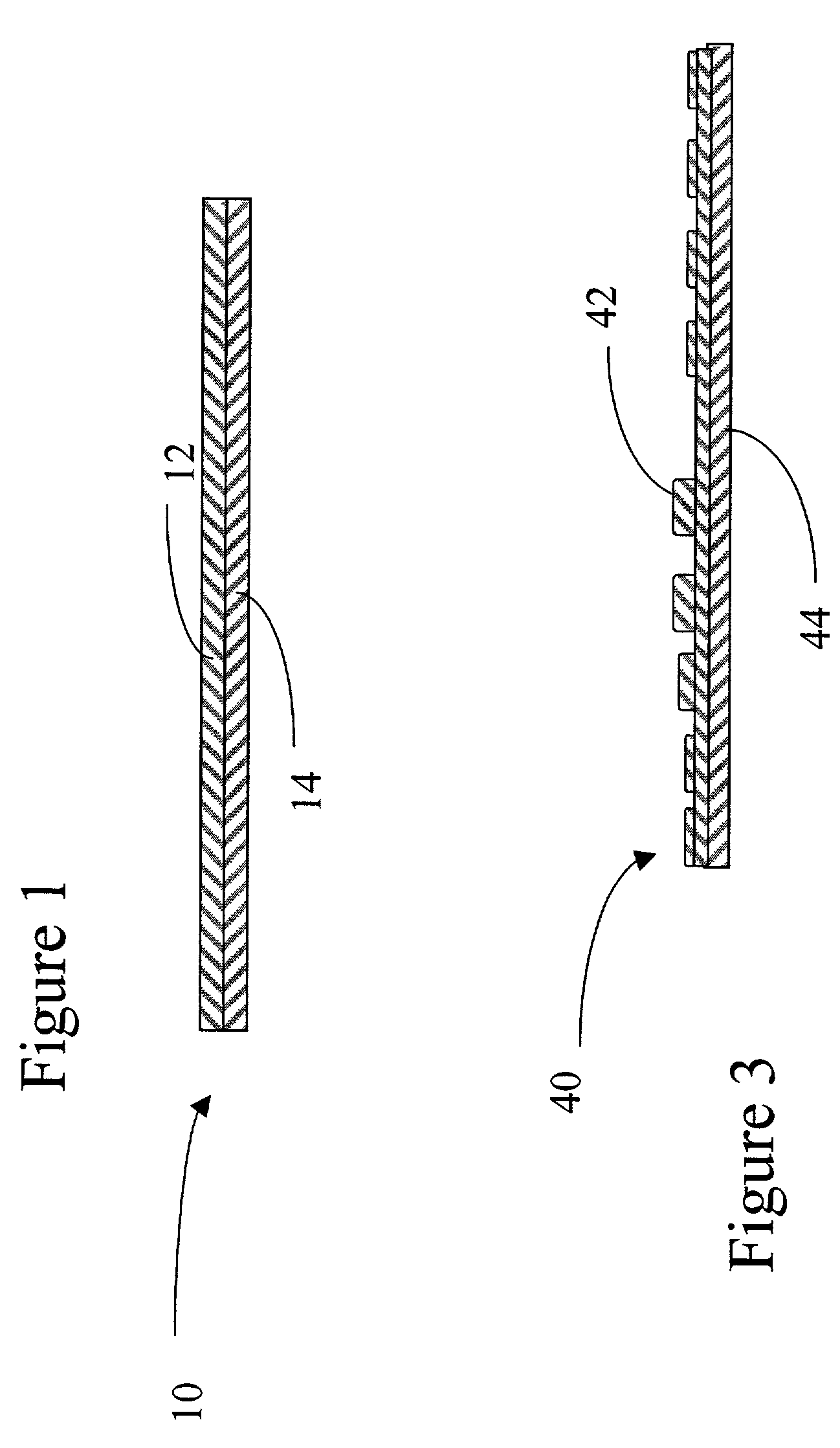
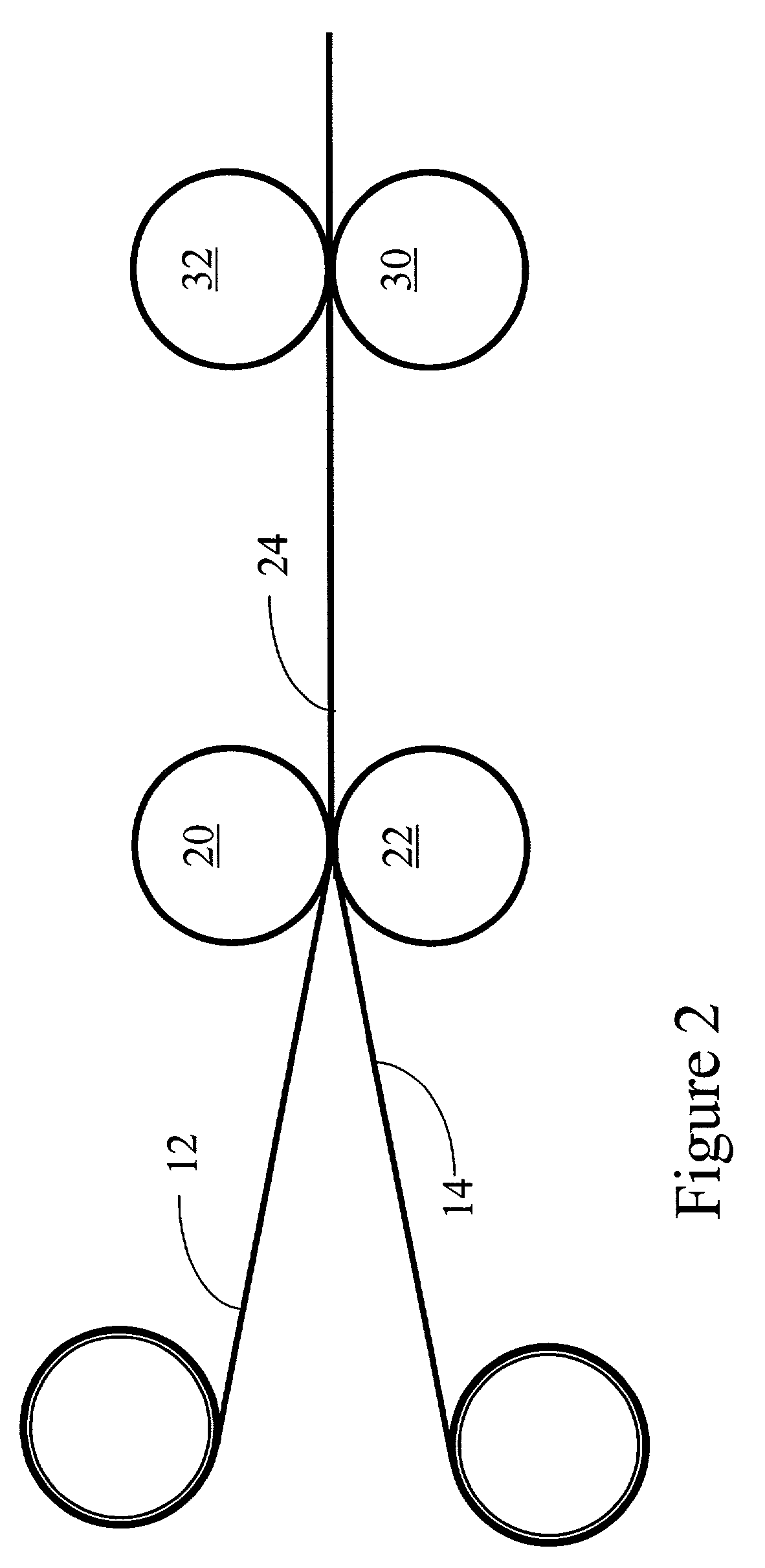
[0083]This example illustrates the production of a composite stock material, suitable for embossing to form fuel cell fluid flow field plates, and the like. Two sheets of resin impregnated graphite foil are provided. One consists of a material that has a thickness of 1.0 mm and a density of 0.75 grams / cc. The other has a thickness of 1.0 mm and a density of 1.0 grams / cc. The sheets are layered and then compressed between a pair of nip rolls spaced at 1.5 mm, with the result that the two sheets are consolidated into a single composite having zones of differing densities through thickness.

example 2

[0084]The procedure of Example 1 is repeated, but this time the first layer is 0.25 mm in thickness, has a density of 1.0 grams / cc and is not resin impregnated.

example 3

[0085]The procedure of Example 1 is repeated, but this time one of the layers is not a solid sheet but rather contains cut-out regions, in this one case, a frame of material. This allows for the creation of a single composite having zones of differing densities through thickness and in-plane.


PUM

PropertyMeasurementUnit
densityaaaaaaaaaa
densityaaaaaaaaaa
densityaaaaaaaaaa

Abstract

An improved method enables preparation of articles for a variety of applications, including embossing or otherwise shaping to form a variety of articles. A plurality of thin, preferably resin-impregnated, flexible graphite sheets are arranged to form zones in a composite material having a graded density or other characteristic. Variation of properties between zones in the stock material formed is useful for achieving a desired set of properties in the formation of articles such as those useful in electrochemical fuel cells and double-layer capacitors.

Description

TECHNICAL FIELD[0001]The invention relates to a material which can be used in preparing flexible graphite articles of controlled properties, such as density, to facilitate a further processing step. In a preferred form, the material will provide a stock material useful for embossing into a precise surface pattern or structure, while providing close tolerance control of important product characteristics. More particularly, the invention relates to methods and materials enabling the preparation of shaped elements having predetermined density gradation and / or detail necessary for their intended functions. The invention enables the achievement and control of density and / or structural definition such that performance per unit weight can be improved in an array of final products, at least some of which are useful as components in electrochemical supercapcitors and fuel cells.BACKGROUND OF THE INVENTION[0002]Electrochemical devices like supercapacitors and fuel cells are foreseen by some a...

Claims


Application Information

Patent Timeline
Patent Type & Authority Patents(United States)
IPC IPC(8): B32B7/02B32B9/00H01G9/00H01G9/155H01M8/02
CPCB32B9/00C04B35/536C08J5/24H01G9/155H01M8/0234H01M8/0241H01M8/0245C04B35/522Y10T428/2982H01M8/0206H01M8/0228Y02E60/13Y02E60/50C04B2235/787Y10T156/1023Y10T156/1041Y10T428/30Y10T428/24802Y10T428/24942Y10T428/249953H01G11/32H01G11/26H01G11/38C08J5/241C08J5/242B32B9/007B32B38/06B32B38/08B32B5/026B32B5/022B32B9/041B32B2313/04B32B15/04B32B2307/724B32B2307/726B32B2307/72B32B9/04B32B2307/302B32B2307/202
Inventor MERCURI, ROBERT ANGELOKLUG, JEREMYGETZ, MATTHEW GEORGEWEBER, THOMAS WILLIAM
Owner GRAFTECH INT HLDG INC
Why Eureka
Try Eureka