Color emission device

mission technology, applied in the direction of discharge tube luminescnet screen, discharge tube/lamp details, incadescent envelope/vessel, etc., can solve the problems of difficult to obtain a color emission device with a high efficiency, short durability and low efficiency of red pixels, and the element of a very complicated structure is required. , to achieve the effect of excellent color purity, long durability and luminescent efficiency

Inactive Publication Date: 2007-06-19
IDEMITSU KOSAN CO LTD
View PDF13 Cites 13 Cited by
  • Summary
  • Abstract
  • Description
  • Claims
  • Application Information

AI Technical Summary

Benefits of technology

[0025]According to the invention, the number of effective photons that contribute to light emission of a red converting member can increase because a peak of emission spectrum of organic EL element coincides with that of excitation spectrum of color converting member in red pixels. As a result, the luminescence intensity, that is, luminance of red pixels can be enhanced.
[0026]Consequently the red intensity can be high even if the same voltage is applied to each color pixel. Further imbalanced deterioration of the organic EL element can be suppressed and high red intensity can be maintained for long time. In addition, the luminance of the color emission device can be maintained high for long time without a complicated pixel pattern.
[0027]The color emission device of the invention may have each color filter that cuts off unnecessary color components, thereby improving the reproducibility of each color.
[0031]Thus if the ratio is within the range from 9:1 to 5:5, the luminescence intensity (luminance) of red pixels relatively increases, thereby ensuring the white balance in the color emission device.
[0035]Such peaks enhance not only the luminance of red pixels but also the luminance and color purity of blue and green pixels in the same element, thereby ensuring the white balance.

Problems solved by technology

However it is difficult to obtain a color emission device with a high efficiency and small change in white balance with time, since the pixels of three colors have different durability, particularly red pixels have a short durability and low efficiency.
However in order to contain a red component in higher intensity than blue and green components, an element of very complicated structure is required.
As a result, it is difficult to manufacture devices with a good reproducibility.
However in a color emission device thus constructed, the efficiency of converting blue light to red light is lower than that of converting blue light to green light, since the energy gap is larger when converting blue light to red light.
However the arrangement pattern of pixels is complicated since the area ratios of color pixels are different from each other.
However if only the luminance of red pixels is increased, only the organic EL elements in the red pixels are degraded so that the luminance of red pixels cannot be maintained high.
However there is no combination of fluorescent dye and binder that can satisfy both high converting efficiency and reliability against environment such as heat and light among known dyes and binders at present.
If an attempt is made to obtain a high converting efficiency, the material is inevitably unstable for environment.
If an attempt is made to obtain a high reliability, its converting efficiency is inevitably reduced.
Further the degradation of a red converting member adversely affects the color stability of whole the color emission device.
However in the above method, the luminescent efficiency of an organic EL element and converting efficiency of color converting member reach the limits.
Thus, if color filters are used to remove unnecessary light for the improvement of color purity, the luminescent efficiency of a color emission device becomes extremely low.

Method used


Image

  • Color emission device
  • Color emission device
  • Color emission device

Examples


first embodiment

[0150]Referring to the drawings, an embodiment of the invention will be described.

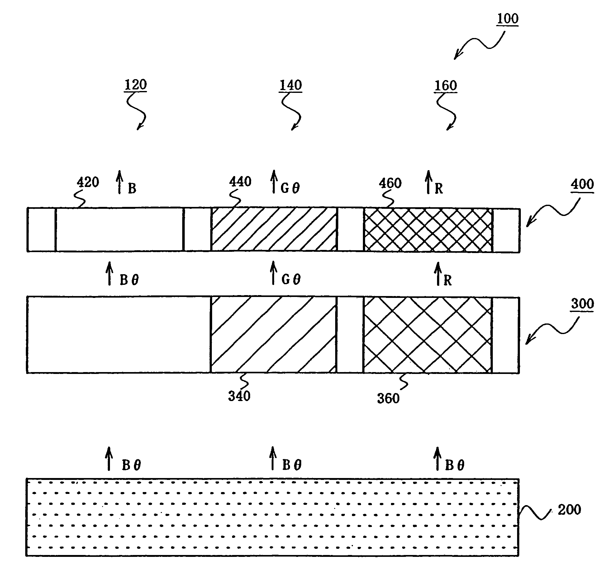
[0151]FIG. 1 is a diagram of a color emission device according to an embodiment of the invention. In this figure, numeral 100 denotes a color emission device, 200 an organic EL element emitting light containing a component with a peak in the blue range (blue component) (B) and a component (θ) with a peak in the range other than blue range, for example 500 to 600 nm, 300 a color converting member containing a fluorescent dye, and 400 a color filter. Numeral 120 denotes a blue pixel, 140 a green pixel, and 160 a red pixel.

[0152]The color converting member 300 contains a green converting member 340 and a red converting member 360. When the green converting member 340 receives light emitted from the organic EL element, it absorbs a blue component (emitting component having a wavelength of 400 to 500 nm) to emit fluorescence of green component (500 to 600 nm). When the red converting member 360 receives lig...

embodiment 2

SIMULATION

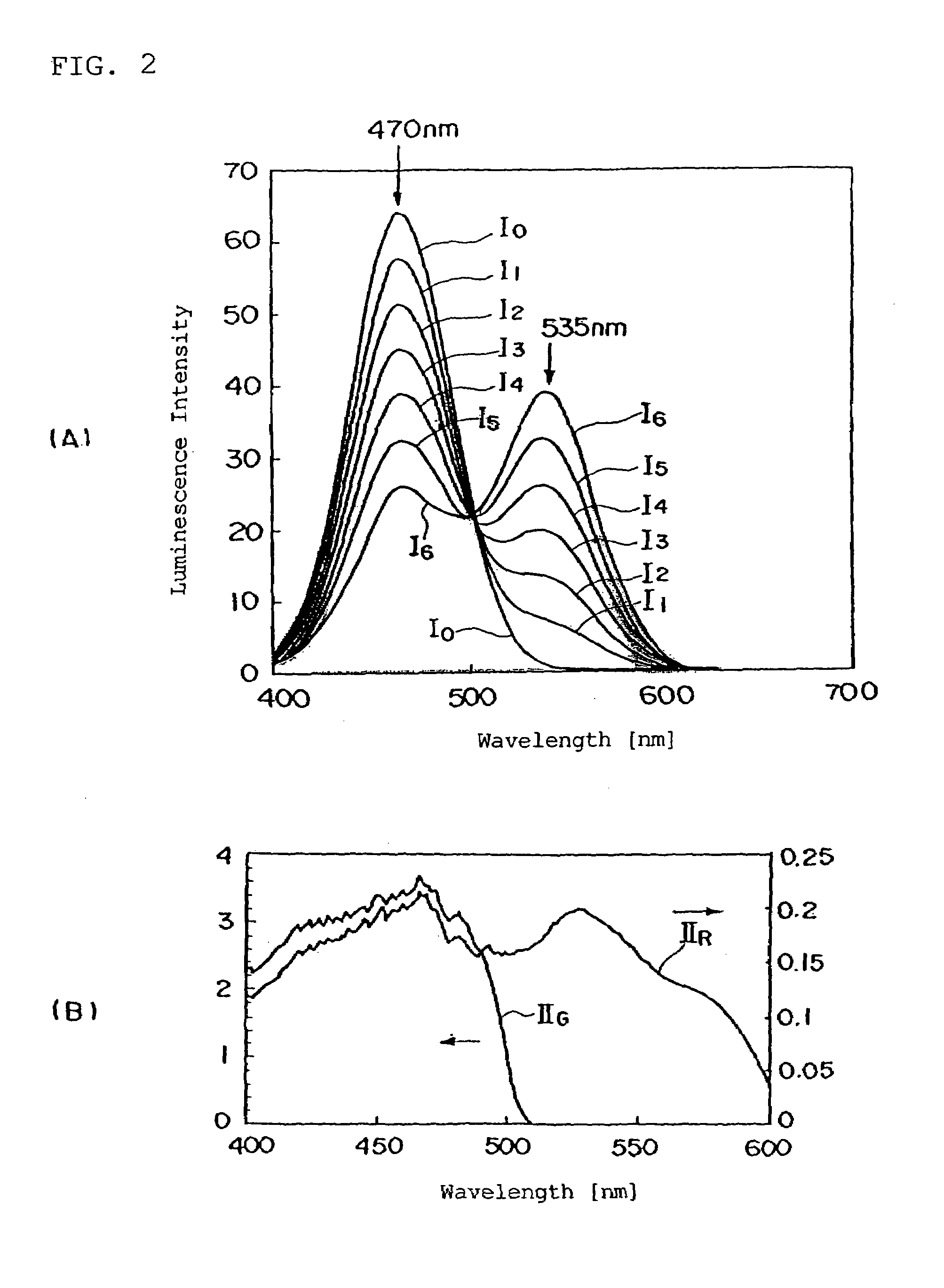
[0164]Furthermore, white balance (balance between luminescence intensities of red, green and blue colors in the case of white display) of an organic EL element with an emission spectrum having peaks in the blue range and 500 to 600 nm range in the color emission device shown in FIG. 1 was obtained by simulation.

(Simulation Method)

[0165]The simulation method herein is a method for obtaining emission spectra taken out from the color filter in the color emission device shown in FIG. 1 without actual measurement, which method is found by the inventors. Details thereof are described in Japanese Patent Application No. 2000-360187.

[0166]According to the method, the emission spectrum WL(λ) f light taken out from a color filter can be obtained from the following equation:

WL(λ)={w(λ)·10−Abs(λ)+lu(λ)·F / F0}·TCF(λ)

F / F0={∫·λw(λ)·EX(λ)dλ} / {∫·λel(λ)·EX(λ)dλ}

[0167]wherein F0 represents the number of effective photons which contribute to light emission of a color converting member in the ca...

embodiment 3

[0201]FIG. 5 is a diagram showing a color emission device according to another embodiment of the invention. In this figure, numeral 40 denotes a color emission device, 50 a luminescence element, 62 a blue converting member, 64 a green converting member, 66 a red converting member.

[0202]The luminescence element 50 emits a blue component and a yellow to red component at a certain peak intensity ratio.

[0203]The blue converting member 62 receives light from the luminescence element 50 and emits light of blue component. The green converting member 64 receives light from the luminescence element 50 and emits light of green component. The red converting member 66 receives light from the luminescence element 50 and emits light of red component.

[0204]Each color converting member is constructed of a fluorescent dye that absorbs a certain part of light emitted from the luminescence element 50 to emit the other fluorescence, a color filter that cuts off light of a certain color and improves the...


PUM


Abstract

An organic EL element (200) emits light containing a blue component (B) and a component (θ) with a peak in 500 to 600 nm. A red converting member (360) has an excitation spectrum with a peak in 500 to 600 nm. The red converting member receives light from the organic EL element (200) and converts the blue component (B) to a red component (R). At this time, the luminance of the red component (R) is enhanced since the member (360) is strongly excited by the component (θ). As a result, the white balance of three colors is improved. Therefore a color emission device (100) can be provided where the intensity of red light is enhanced.

Description

TECHNICAL FIELD[0001]This invention relates to a color emission device, particularly a color emission device suitable for a color display, which device uses an organic electroluminescence element (organic EL element).BACKGROUND ART[0002]When making color emission devices such as televisions or color display elements used in displays for computers, portable telephones and so on by using luminescence elements such as organic EL elements, pixels emitting light of three primary colors, blue, green and red must be formed. There are the following roughly classified three ways for the formation of three pixels but these ways have the following problems.A. Three Color Applying Way[0003]This way is to arrange blue, green and red luminescence elements on a screen respectively.[0004]However it is difficult to obtain a color emission device with a high efficiency and small change in white balance with time, since the pixels of three colors have different durability, particularly red pixels have...

Claims


Application Information

Patent Timeline
Patent Type & Authority Patents(United States)
IPC IPC(8): H01J1/62H01L27/32H01L51/50
CPCH01L27/322H01L51/5036H01L27/3295H01L27/3281H10K59/38H10K59/17H10K59/173H10K50/125H05B33/14H05B33/12
Inventor KUMA, HITOSHIEIDA, MITSURUHOSOKAWA, CHISHIOFUKUOKA, KENICHI
Owner IDEMITSU KOSAN CO LTD
Why Eureka
Try Eureka