Temperature-controlled flexible optical circuit for use in an erbium-doped fiber amplifier and method for fabricating the flexible optical circuit

a technology of erbium-doped fiber amplifier and flexible optical circuit, which is applied in the direction of optical elements, instruments, optical waveguide light guides, etc., can solve the problems of reducing the overall outline of the packag

Inactive Publication Date: 2007-06-19
SANMINA-SCI CORPORATION
View PDF19 Cites 31 Cited by
  • Summary
  • Abstract
  • Description
  • Claims
  • Application Information

AI Technical Summary

Problems solved by technology

Unfortunately, there are a number of disadvantages associated with using the bobbin 106 to hold the optical fiber 108.
Secondly, the bobbin 106 itself is bulky and restricts the overall outline of the package 110.
As such, the custom-designed bobbin 106 delays and adds complexity to the design of the EDFA 100 and can also adversely affect the operability of the EDFA 100.
Unfortunately, there are a number of disadvantages associated with using the fixture 210 to wrap the optical fiber 206 and for using the wire / string 208 to contain the optical fiber 206.
Secondly, the optical fiber 206 may be stressed if the optical fiber 206 is wrapped too tightly around the fixture 210 and also difficult to remove.
As such, the custom-designed fixture 210 delays and adds complexity to the design of the EDFA 200 and the use of wire / string 208 to hold the loose coil of optical fiber 206 can adversely affect the operability of the EDFA 200.
However, this results in a change in total output power which is unacceptable in most designs.
The disadvantage of this technique is that total gain of the EDFA would have to be increased in order to compensate for loss resulting from the attenuator.
These devices are expensive, increasing the cost of the system, and their use also results in signal loss.
Also, gain-flattening filters (“GFF”s) have been used to attempt to compensate for temperature-induced variation in gain, however, such filters are themselves temperature dependent making them inappropriate for temperature compensation of the overall gain.
However, current methods of maintaining constant temperature of an optical fiber used in erbium-doped fiber amplifiers are bulky, and increase thermal resistance and assembly time.
In addition, to the lengthy time to produce such a temperature-controlled optical fiber for use in an EDFA, each time a new amplifier is designed, along with a new bobbin or spool, a new heating element or coil must also be developed increasing design time.
Moreover, the heating element would increase system power consumption.

Method used


Image

  • Temperature-controlled flexible optical circuit for use in an erbium-doped fiber amplifier and method for fabricating the flexible optical circuit
  • Temperature-controlled flexible optical circuit for use in an erbium-doped fiber amplifier and method for fabricating the flexible optical circuit
  • Temperature-controlled flexible optical circuit for use in an erbium-doped fiber amplifier and method for fabricating the flexible optical circuit

Examples


Embodiment Construction

[0028]The various embodiments of the present invention and their advantages are best understood by referring to FIGS. 4 through 8 of the drawings. The elements of the drawings are not necessarily to scale, emphasis instead being placed upon clearly illustrating the principles of the invention. Throughout the drawings, like numerals are used for like and corresponding parts of the various drawings.

[0029]This invention may be provided in other specific forms and embodiments without departing from the essential characteristics as described herein. The embodiments described above are to be considered in all aspects as illustrative only and not restrictive in any manner. The following claims rather than the foregoing description indicate the scope of the invention.

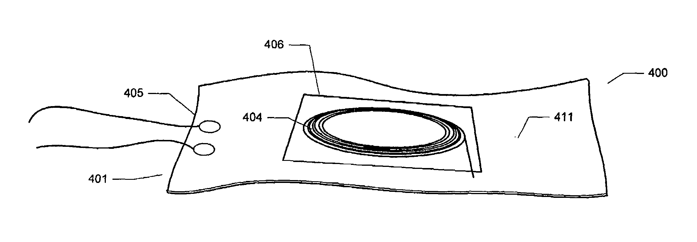
[0030]Referring to FIG. 4, a temperature-controlled flexible optical circuit 400 according to the present invention comprises flexible heater circuit 405. Heater circuit 405 comprises a heating element 411 which is a thin, flex...


PUM


Abstract

A temperature-controlled flexible optical circuit includes a length of pre-fabricated optical fiber secured to a partially flexible heater circuit for heating and maintaining the optical fiber at a substantially constant temperature. Heater circuit may also comprise temperature sensors.

Description

CROSS REFERENCE TO RELATED APPLICATIONS[0001]This application is a continuation-in-part of co-owned U.S. application Ser. No. 10 / 127,089 filed Apr. 22, 2002, now U.S. Pat. No. 6,829,426.BACKGROUND[0002]1. Field[0003]The present invention relates generally to a flexible optical circuit for use in a fiber amplifier and, in particular, to a flexible circuit that is temperature-controlled.[0004]2. Description of Related Art[0005]An erbium-doped fiber amplifier (EDFA) is basically an optical repeater device that functions to boost the amplitude of optical signals traveling through a fiber optic communications system. In particular, the EDFA incorporates a variety of components including a laser diode, a multiplexer and an optical fiber which is doped with the rare earth element erbium. The laser diode emits light having an infrared wavelength of 980 nm or 1480 nm that is passed through the multiplexer into the erbium-doped optical fiber. The emitted light excites the erbium atoms in the ...

Claims


Application Information

Patent Timeline
Patent Type & Authority Patents(United States)
IPC IPC(8): G02B6/44H04B10/12G02BG02B6/12G02B6/36H01S3/042H01S3/067H01S3/102H04B10/17
CPCG02B6/3676H01S3/042H01S3/06704H01S3/06754H01S3/102H04B10/291G02B6/3608
Inventor ARELLANO, AARON G.
Owner SANMINA-SCI CORPORATION
Why Eureka
Try Eureka