Programmable low-voltage differential signaling output driver

a low-voltage differential signaling and output driver technology, applied in the direction of gated amplifiers, logic circuit coupling/interface arrangements, pulse techniques, etc., can solve the problem of unadjustable output current, and achieve the effect of fast edge rate and boost the edge rate of lvds outpu

Active Publication Date: 2007-06-26
TAHOE RES LTD
View PDF16 Cites 53 Cited by
  • Summary
  • Abstract
  • Description
  • Claims
  • Application Information

AI Technical Summary

Benefits of technology

[0009]A programmable LVDS output driver may be provided in accordance with the present invention. The programmable LVDS output driver may include circuitry for tri-stating the output of the output driver, which allows the output of the output driver to be disabled independent from the input. For example, two p-type transistors may be coupled to the current source, such that when ground is applied to the gates of the p-type transistors, the source current passes through one of the p-type transistors (depending on how the current is steered). When the source voltage is applied to gates of the p-type transistors, the output driver is prevented from passing current. When the output driver is disabled, the output impedance also becomes very high. This allows another output driver coupled to the receiver to transmit data to the receiver without being affected by the presence of the output driver.
[0010]The programmable LVDS output driver may also support hot socketing. Hot socketing allows the output driver to be tri-stated upon insertion even if the output driver has not yet been powered. This prevents the output driver from interfering with other signals being transmitted to the receiver at the time it is inserted.
[0011]The programmable LVDS output driver may also include programmable current sources. With fixed current sources, the output current is not adjustable. The source current may be adjusted to reduce the output current and power consumption of the output driver, or to compensate for current diverted to additional circuitry within the output driver, such as impedance circuitry.
[0012]The programmable LVDS output driver may also include impedance circuitry for adjusting the output impedance. To maximize high frequency performance, the output impedance of the output driver should be matched with that of the board traces coupled to the output driver. An impedance circuit may be coupled between the outputs of the output driver to not only adjust the impedance of the output driver, but also to limit the amount of current diverted from the output.
[0014]The programmable LVDS output driver may also include pre-emphasis circuitry. Pre-emphasis circuitry may boost the edge rate of the LVDS output. Typically, edge rates of LVDS outputs are slow, and at high frequencies, the receiver may incorrectly identify the current bit because the bit has not risen (or fallen) quickly enough to be identified. A pre-emphasis circuit may be coupled to each output of the output driver, such that when the pre-emphasis circuit detects a transition in the input, the pre-emphasis circuit produces a small burst of current. The superposition of the output current and the current produced by the pre-emphasis circuit results in a signal with a fast edge rate.

Problems solved by technology

With fixed current sources, the output current is not adjustable.

Method used


Image

  • Programmable low-voltage differential signaling output driver
  • Programmable low-voltage differential signaling output driver
  • Programmable low-voltage differential signaling output driver

Examples


Embodiment Construction

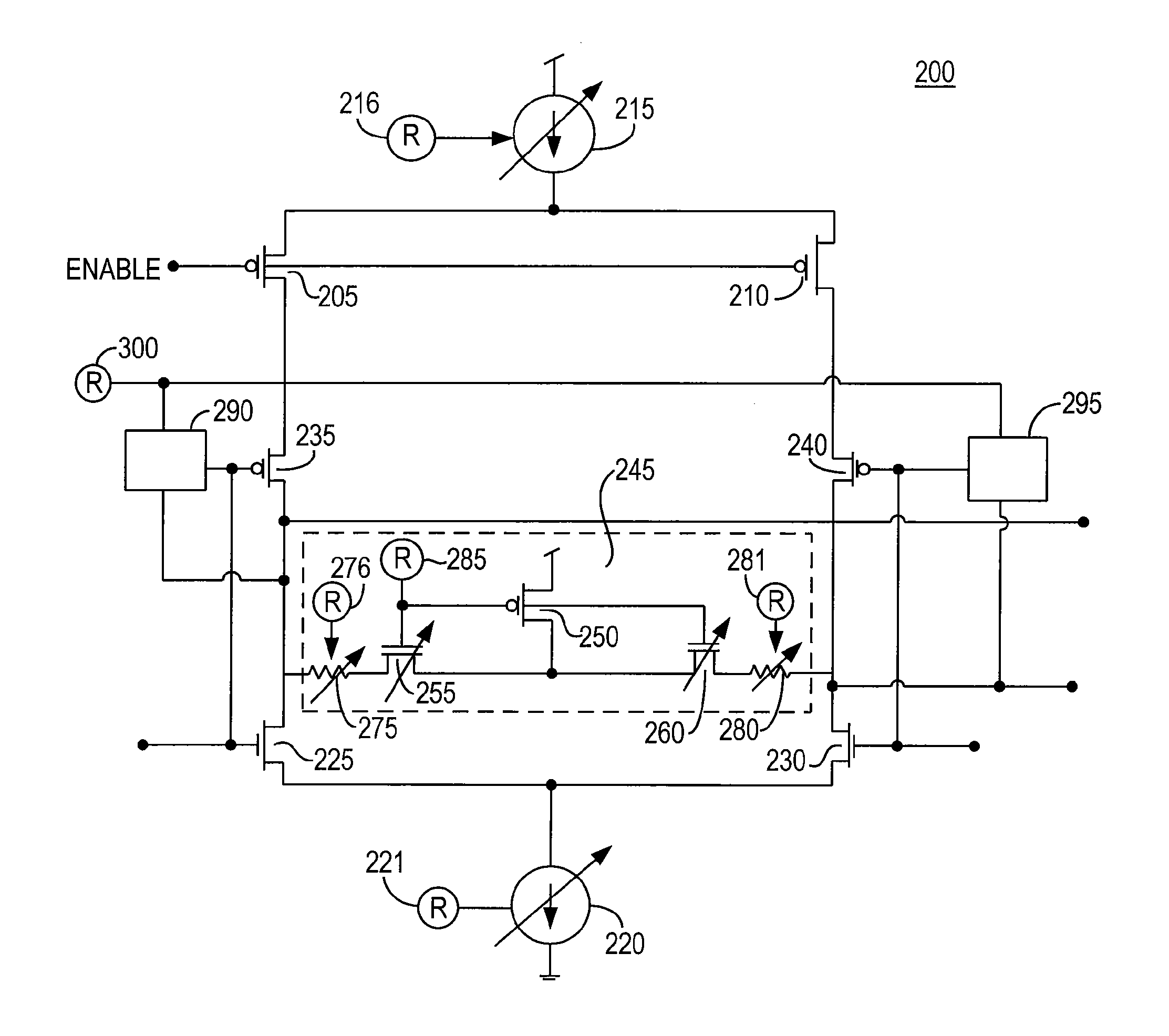
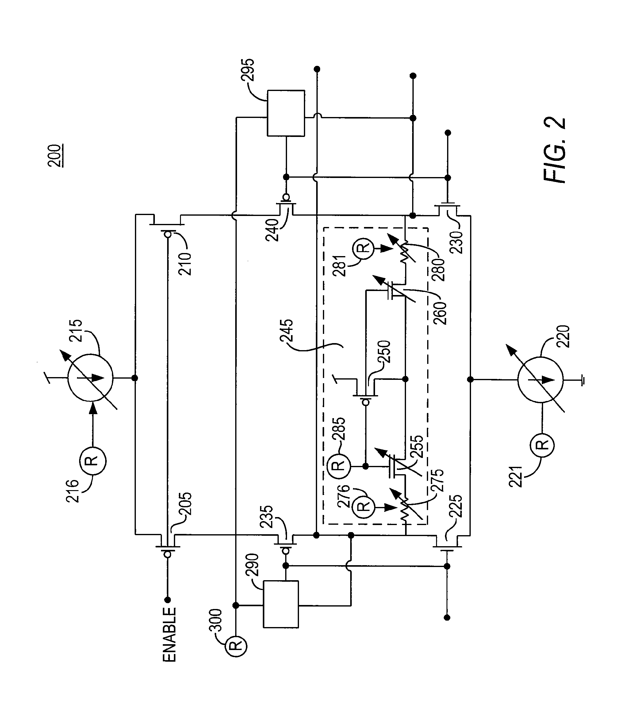
[0018]For purposes of illustration and not limitation, the present invention will be described in connection with a low-voltage differential signaling (LVDS) system. It should be noted that the principles of this invention may be applicable to other standards relating to the transmission of data.

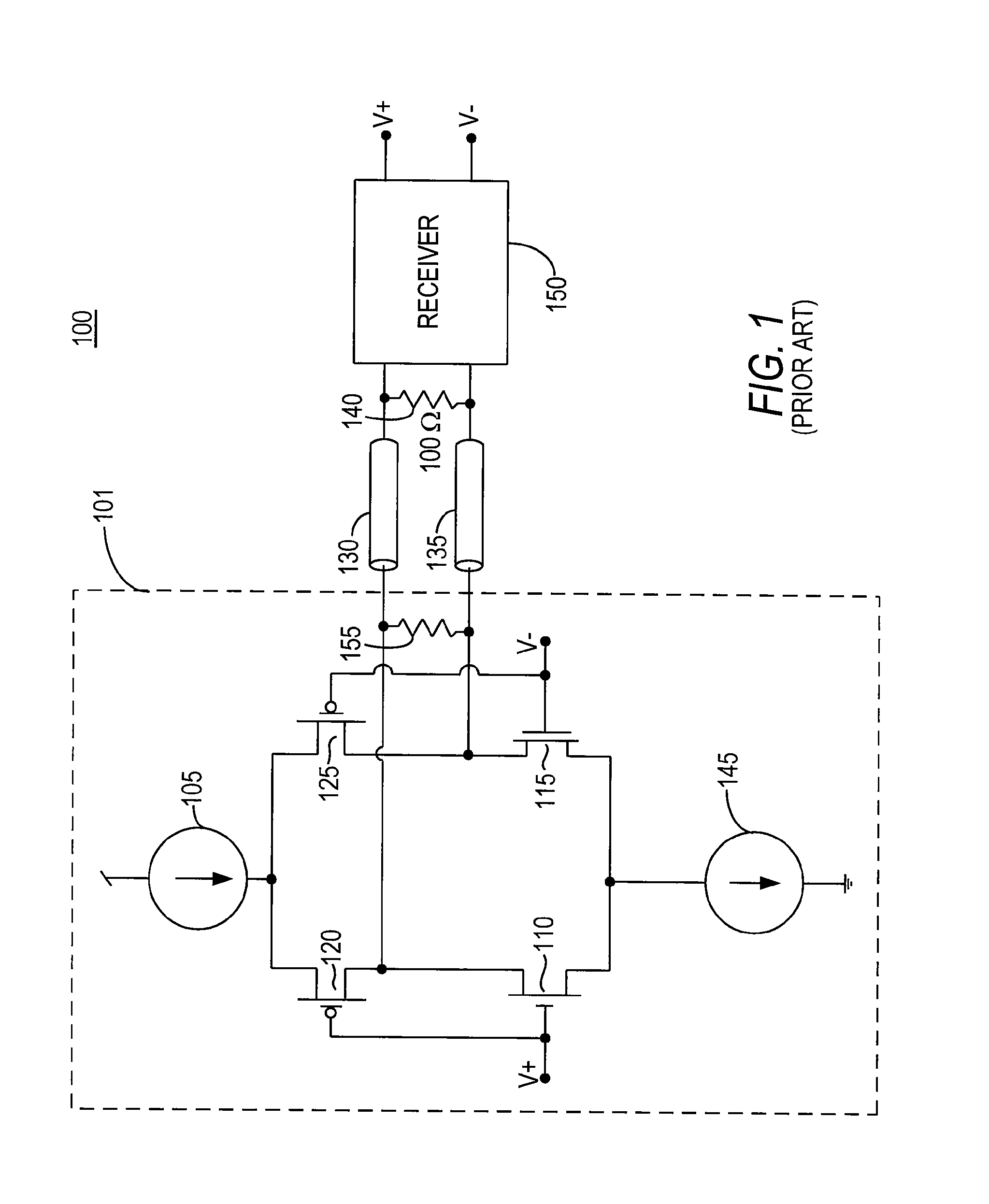
[0019]Low-voltage differential signaling (LVDS) allows an output driver to transfer data to a receiver at high speeds, while only consuming a small amount of power. LVDS signaling may be accomplished by steering current from the output driver to the receiver in one of two opposing current paths. (Current flowing in one direction indicates a high bit is being transferred and current flowing in the opposite direction indicates a low bit is being transferred.) The current paths may be terminated by a termination resistor at the receiver. The receiver may detect the direction of the current flowing across the resistor (i.e., by measuring the voltage drop across the termination resistor) to deter...


PUM


Abstract

The present invention relates to a programmable low-voltage differential signaling (LVDS) output driver. The programmable LVDS output driver may include circuitry for tri-stating the output to allow several programmable LVDS output drivers to be coupled to a single receiver. The programmable LVDS output driver may also include programmable current sources for varying the output current, as well as providing additional current to circuitry within the driver (e.g., impedance circuitry). The programmable LVDS output driver may also include an impedance circuit for adjusting the output impedance of the output driver, while only diverting a small amount of source current. The current diverted by the impedance circuit may be compensated for by increasing the source current from the programmable current sources. The programmable LVDS output driver may also include pre-emphasis circuitry for boosting the edge rates of output signals.

Description

BACKGROUND OF THE INVENTION[0001]The present invention relates to a low-voltage differential signaling (LVDS) output driver. More particularly, this invention relates to an LVDS output driver with a tri-statable output, programmable output current, programmable output resistance, and programmable pre-emphasis circuitry.[0002]Low-voltage differential signaling (LVDS) is one of many I / O standards used in high-speed data transmission. A basic LVDS system includes an output driver and a receiver, connected by a pair of leads (e.g., copper traces, transmission lines, etc.) each having a fixed impedance (e.g., 50Ω). The output driver converts a differential logic signal into a low-level current, which, depending on the polarity of the signal, flows from one of two outputs towards the receiver. The current passes through a termination resistor at the receiver and flows back to the output driver. The receiver detects the direction of the current flow through the termination resistor to dete...

Claims


Application Information

Patent Timeline
Patent Type & Authority Patents(United States)
IPC IPC(8): H03B1/00
CPCH03F1/0205H03F3/45183H03F3/72H03F2200/372H03F2200/513H03F2203/45466H03F2203/45641H03F2203/45686H03F2203/45726H03F2203/7206
Inventor WANG, BONNIESUNG, CHIAKANGNGUYEN, KHAI
Owner TAHOE RES LTD
Why Eureka
Try Eureka