Heat dissipating apparatus having micro-structure layer and method of fabricating the same

a technology of heat dissipating apparatus and microstructure layer, which is applied in the direction of lighting and heating apparatus,foundry moulding apparatus, semiconductor/solid-state device details, etc., can solve the problems of power consumption, heat dissipation, reliability, and the functionality of electronic devices, and achieve the effect of increasing the heat dissipation efficiency of these devices

Inactive Publication Date: 2007-07-03
IND TECH RES INST
View PDF29 Cites 32 Cited by
  • Summary
  • Abstract
  • Description
  • Claims
  • Application Information

AI Technical Summary

Benefits of technology

[0011]To overcome the above drawbacks of conventional technology, an objective of the present invention is to provide a heat dissipating apparatus having a micro-structure layer and a method of fabricating the same, which increase the heat dissipating efficiency thereof.
[0012]Another objective of the present invention is to provide a heat dissipating apparatus having a micro-structure layer and method of fabricating the same, which fabricating method is simple and adaptable to mass production.

Problems solved by technology

During the last decades, semiconductor fabrication techniques have both reduced the size and increased the functionality of electronic devices, but problems in terms of power consumption, heat dissipation, and reliability have inevitably derived from the process of integrating the electronic devices.
The main reason for the limited reliability of the above devices is that the electronic devices are driven by electricity power that is not fully utilized, and the unused portion of power is converted into heat energy, which dramatically raises the temperature of the whole system incorporating these devices.
In the case that the operating temperature goes beyond the range permitted, erratic operation, system failure, and even damage may occur.
Thus, the amount of heat generated in the course of operation is significantly huge to easily result in their operating temperature exceeding the permitting range.
Compounding the problem, along with the trend of miniaturized electronic devices, heat dissipating apparatus has shrunk the size as well to accommodate the desire for smaller products, which presents a big challenge to the fabricating technology in this field in terms of effective heat dissipation and product reliability.
While such heat dissipating apparatus is targeted for using on the miniaturized electronic devices, having the capillary structures dimensioned in micron (μm) scale adds more difficulty to precisely control the fabricating method.
However, a serious drawback associated with the fabrication method is found in the actual production, since the dimension of the capillary structure is not precisely controlled by such sintering method.
For a capillary structure with dimensional precision required at the μm scale, the final sintered product usually does not meet the dimensional precision as required in the original design.
Therefore, the heat dissipating efficiency is significantly degraded.
However, the process described above only solves the problem associated with forming the capillary structure.
Other drawbacks remain to be solved, such as the density of the applied copper is relatively low compared to regular plated copper due to the high temperature used in injection molding resulting in a much lower thermal coefficient.
Therefore, although heat can be dissipated by liquid-gas phase transition according to the process above, the efficiency of heat dissipation as a whole still awaits further improvement, and current needs for heat dissipating of electronic devices are not satisfied.

Method used


Image

  • Heat dissipating apparatus having micro-structure layer and method of fabricating the same
  • Heat dissipating apparatus having micro-structure layer and method of fabricating the same
  • Heat dissipating apparatus having micro-structure layer and method of fabricating the same

Examples


Embodiment Construction

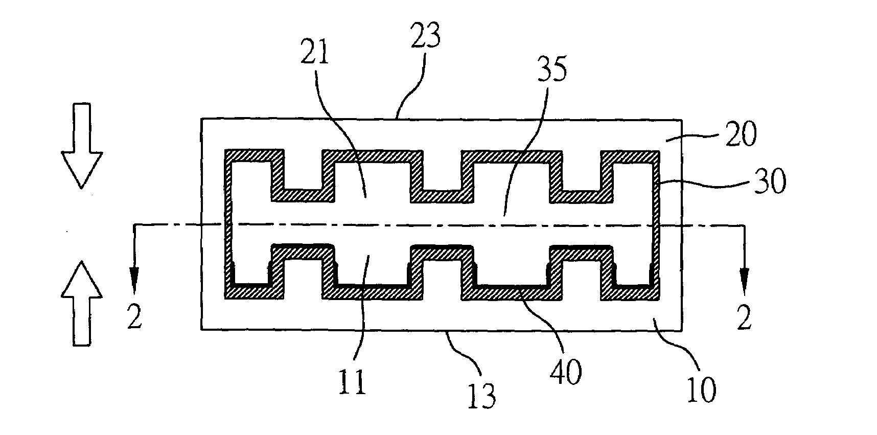
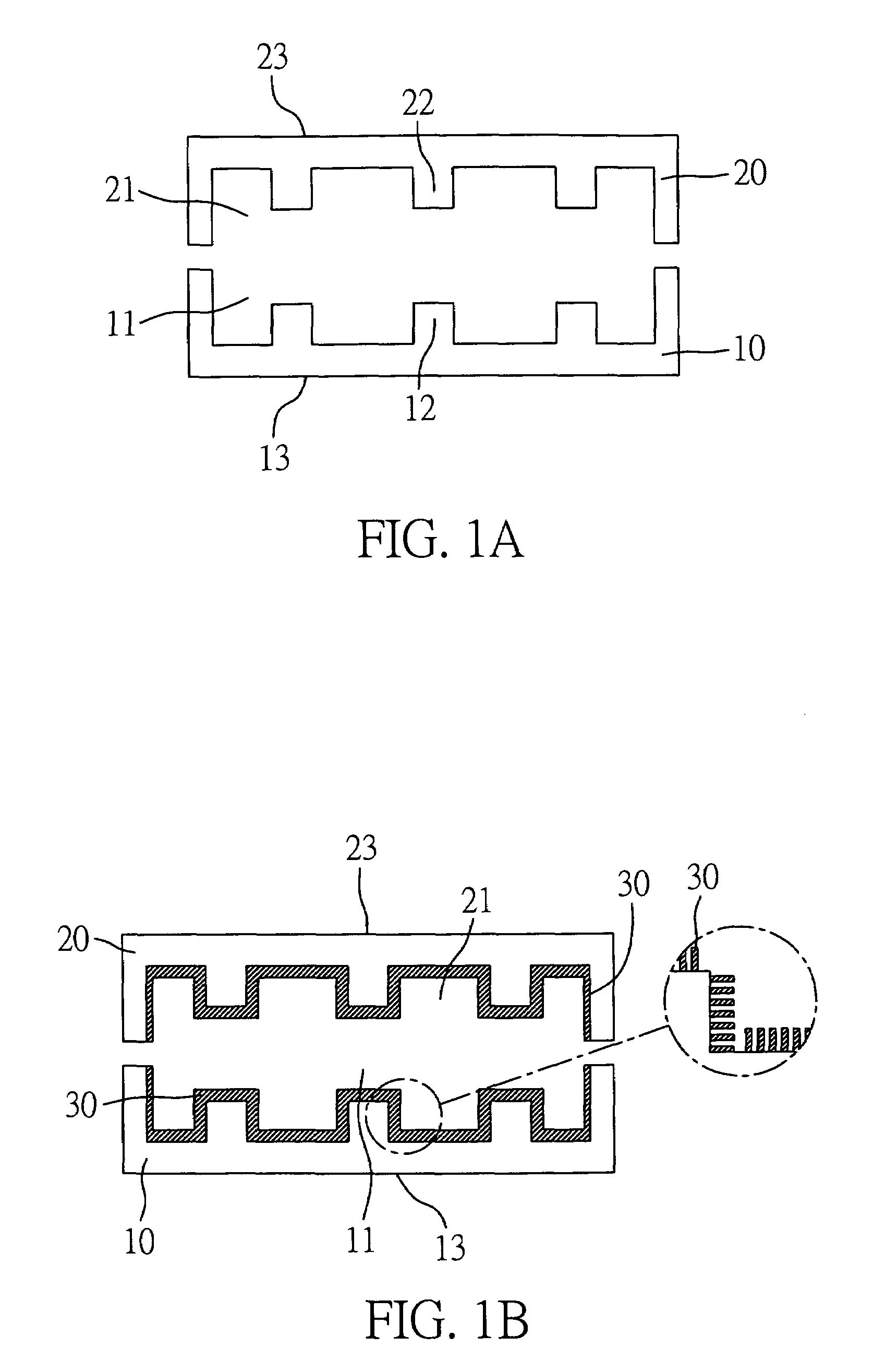
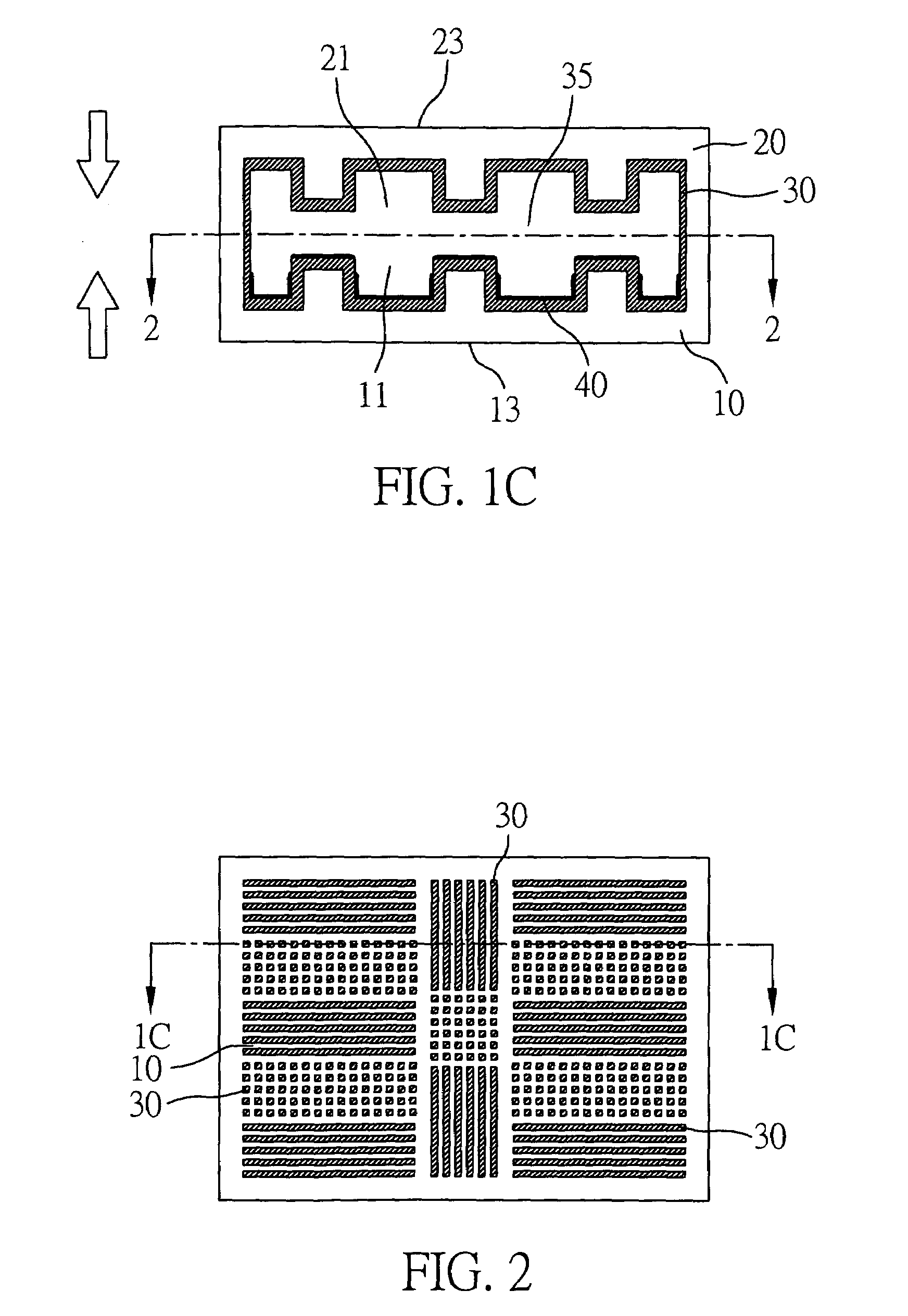
[0025]FIGS. 1A to 1C illustrate the fabrication method of a heat dissipating apparatus having a micro-structure layer in accordance with the present invention. Firstly, referring to FIG. 1A, a first substrate 10 and a second substrate 20 of equal dimension are respectively provided. Both of the first substrate 10 and a second substrate 20 are made of a highly-dense metal block, and the metal block may be a highly heat conductive material such as copper, silver, aluminum, and so on. The first substrate 10 is defined with a first opening 11 having an inner wall formed with a geometrically structured pattern 12, such that differing profile heights are provided in the inner wall of the first opening 11. In contrast, a heat absorbing surface 13 is defined on an outer surface of the first substrate 10 opposite to the first opening 11. The second substrate 20 comprises a similar structure to that of the first substrate 10. The second substrate 20 is defined with a second opening 21 having ...


PUM

PropertyMeasurementUnit
heat conductiveaaaaaaaaaa
sizeaaaaaaaaaa
temperatureaaaaaaaaaa

Abstract

The present invention relates to a heat dissipating apparatus having micro-structure layer and method for fabricating the same. The method provides two highly heat conductive members having structure patterns. A highly heat conductive material is coated on the structured patterns by means of injection molding for forming a micro-structure layer. The two highly heat conductive members are assembled to form a heat dissipating apparatus having micro-structure layer. The heat dissipating apparatus comprises a main body composed of the highly heat conductive members. The main body forms an accommodating cavity, and inner surfaces of the accommodating cavity form the micro-structure layer. A working fluid is filled into the accommodating cavity for transferring heat from a heat absorbing surface to a heat dissipating surface.

Description

BACKGROUND OF THE INVENTION[0001]1. Field of the Invention[0002]The present invention relates generally to a heat dissipating apparatus having a micro-structure layer and method of fabricating the same, and more particularly, to a heat dissipating apparatus having a micro-structure layer and method of fabricating the same employing a liquid-gas phase transition to dissipate heat.[0003]2. Description of the Related Art[0004]During the last decades, semiconductor fabrication techniques have both reduced the size and increased the functionality of electronic devices, but problems in terms of power consumption, heat dissipation, and reliability have inevitably derived from the process of integrating the electronic devices.[0005]The main reason for the limited reliability of the above devices is that the electronic devices are driven by electricity power that is not fully utilized, and the unused portion of power is converted into heat energy, which dramatically raises the temperature of...

Claims


Application Information

Patent Timeline
Patent Type & Authority Patents(United States)
IPC IPC(8): B23P6/00F28F7/00F28D15/02F28D15/04H01L23/427H05K7/20
CPCB23P15/26F28D15/0233F28D15/0266F28D15/046H01L23/427B23P2700/10Y10T29/49087H01L2924/0002Y10T29/49353Y10T29/4935Y10T29/49083H01L2924/00
Inventor YEH, LAN-KAILIN, CHE-WEITSAI, MING-JYECHEN, SHAO-WENSHYU, JIN-CHERNG
Owner IND TECH RES INST
Why Eureka
Try Eureka