Device for power factor correction in forced switching power supply units

a power factor correction and power supply technology, applied in the direction of ac-dc conversion, efficient power electronics conversion, electric variable regulation, etc., can solve the problem of increasing the losses of output diodes, needing a larger output capacitor, and the inability to optimize dc-dc converter downstream for a constant input voltage, etc. problem, to achieve the effect of improving performan

Active Publication Date: 2007-07-03
STMICROELECTRONICS SRL
View PDF5 Cites 36 Cited by
  • Summary
  • Abstract
  • Description
  • Claims
  • Application Information

AI Technical Summary

Benefits of technology

[0020]The present invention makes it is possible to produce a device for power factor correction in a forced switching power supply unit according to the “tracking boost” embodiment that has better performance than conventional devices.

Problems solved by technology

Nevertheless a boost converter of this type presents some disadvantages, such as an increase in the losses in the output diode, the need for a larger output capacitor, and the impossibility of optimizing the DC-DC converter downstream for a constant input voltage.

Method used


Image

  • Device for power factor correction in forced switching power supply units
  • Device for power factor correction in forced switching power supply units
  • Device for power factor correction in forced switching power supply units

Examples


Embodiment Construction

[0025]Preferred embodiments of the present invention will be described in detail hereinbelow with reference to the attached drawings.

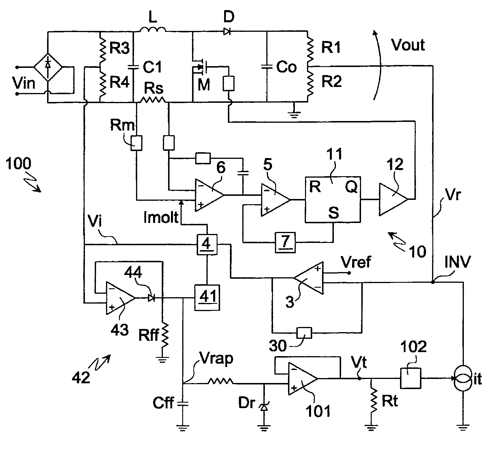
[0026]FIG. 2 shows a circuit diagram of a PFC for a forced switching power supply unit according to a first embodiment of the present invention. The elements of FIG. 2 that are the same as in the circuit of FIG. 1 are indicated with the same reference labels. The PFC comprises a converter 20 provided with a full-wave diode rectifier bridge 2 receiving at its input a mains voltage Vin, a capacitor C1 (that acts as a filter for the high frequency) having its terminals connected to the terminals of the diode bridge 2, an inductance L connected to a terminal of the capacitor C1, a MOS power transistor M having its drain terminal connected to a terminal of the inductance L that is downstream of the inductance and having its source terminal connected to ground, a diode D having its anode connected to the common terminal of the inductance L and the transistor...


PUM


Abstract

A device for power factor correction in a forced switching power supply unit is provided. The device includes a converter and a control device coupled to the converter so as to obtain from an input alternating mains voltage a direct regulated voltage on the output terminal. The converter includes a power transistor, and the control device includes an error amplifier having its inverting terminal coupled to a first signal that is proportional to the regulated voltage and its non-inverting terminal coupled to a reference voltage. A drive circuit of the power transistor is coupled to the output terminal of the error amplifier. The control device also includes a circuit for generating a current signal that is representative of the effective input voltage. The current signal is coupled to the inverting terminal of the error amplifier to vary the regulated voltage in reply to variations in the effective input voltage.

Description

CROSS-REFERENCE TO RELATED APPLICATIONS[0001]This application is based upon and claims priority from prior Italian Patent Application No. MI2004A002004, filed Oct. 21, 2004, the entire disclosure of which is herein incorporated by reference.FIELD OF THE INVENTION[0002]The present invention relates to a device for power factor correction in forced switching power supply units.BACKGROUND OF THE INVENTION[0003]There are conventional devices for the active power factor correction (PFC) for forced switching power supply units used in commonly used electronic devices such as computers, televisions, and monitors, and for supplying fluorescent lamps, that is forced switching pre-regulation stages whose task is to absorb a nearly sinusoidal current from the mains which is also in phase with the mains voltage. Therefore a forced switching power supply unit of the present type comprises a PFC and a converter of direct current into direct current (or “DC-DC converter”) connected to the output o...

Claims


Application Information

Patent Timeline
Patent Type & Authority Patents(United States)
IPC IPC(8): G05F1/70H02M7/155
CPCH02M1/4225H02M2001/0022H02M2001/0025Y02B70/126Y02B70/10H02M1/0022H02M1/0025
Inventor ADRAGNA, CLAUDIOFAGNANI, MAUROGATTAVARI, GIUSEPPE
Owner STMICROELECTRONICS SRL
Why Eureka
Try Eureka