Storage media reading writing system

Inactive Publication Date: 2007-07-03
HITACHI LTD
View PDF19 Cites 8 Cited by
  • Summary
  • Abstract
  • Description
  • Claims
  • Application Information

AI Technical Summary

Benefits of technology

[0007]Accordingly, the inventors investigated the possibility of shortening the length of the cable that connects the magnetic head and the read write IC by installing the read write IC on the arm. However, the installation of the read write IC on the arm increases the weight of the arm, which interferes with the seek operation, and a large size IC is not permitted to be mounted on the arm. From such circumstances, the inventors reach an idea to divide the functions of the conventional read write IC into plural chips, and to install only the IC on the arm that is connected directly to the magnetic head and has a minimum configuration of a read amplifier and a write amplifier to electrically drive the head, whereby the aforementioned problem can be solved.
[0030]According to another aspect of the invention, when the system incorporates a plurality of the heads, a plurality of the first semiconductor integrated circuits are provided corresponding to the number of the heads, and the second semiconductor integrated circuit is provided as a common circuit to a plurality of the first semiconductor integrated circuits. This reduces the number of the chips constituting the system, and facilitates the assembly.

Problems solved by technology

Differently from a semiconductor memory, the magnetic disk drive includes physically movable parts that delay the read and write speed of data, which is disadvantageous, and there is a demand for a still further increase in the speed.
However, the inventors found a problem that an increase of the data transfer speed will accompany a deterioration of the SN ratio relating to the read signal and the write signal.
As the result, the inventors found that the noises of high-frequency components are created at the magnetic head (especially during writing), and in such a configuration that the read write IC is installed on the carriage and the magnetic head located on the front of the arm is connected to the read write IC with a cable, if the length of the cable is very long, it will function as an antenna to pick up high frequency noises; and the noises picked up by the cable deteriorate the SN ratio since a signal transmitted through the cable is very weak.
However, the installation of the read write IC on the arm increases the weight of the arm, which interferes with the seek operation, and a large size IC is not permitted to be mounted on the arm.

Method used


Image

  • Storage media reading writing system
  • Storage media reading writing system
  • Storage media reading writing system

Examples


Embodiment Construction

[0054]Preferred embodiments of the invention will now be described on the basis of the accompanying drawings.

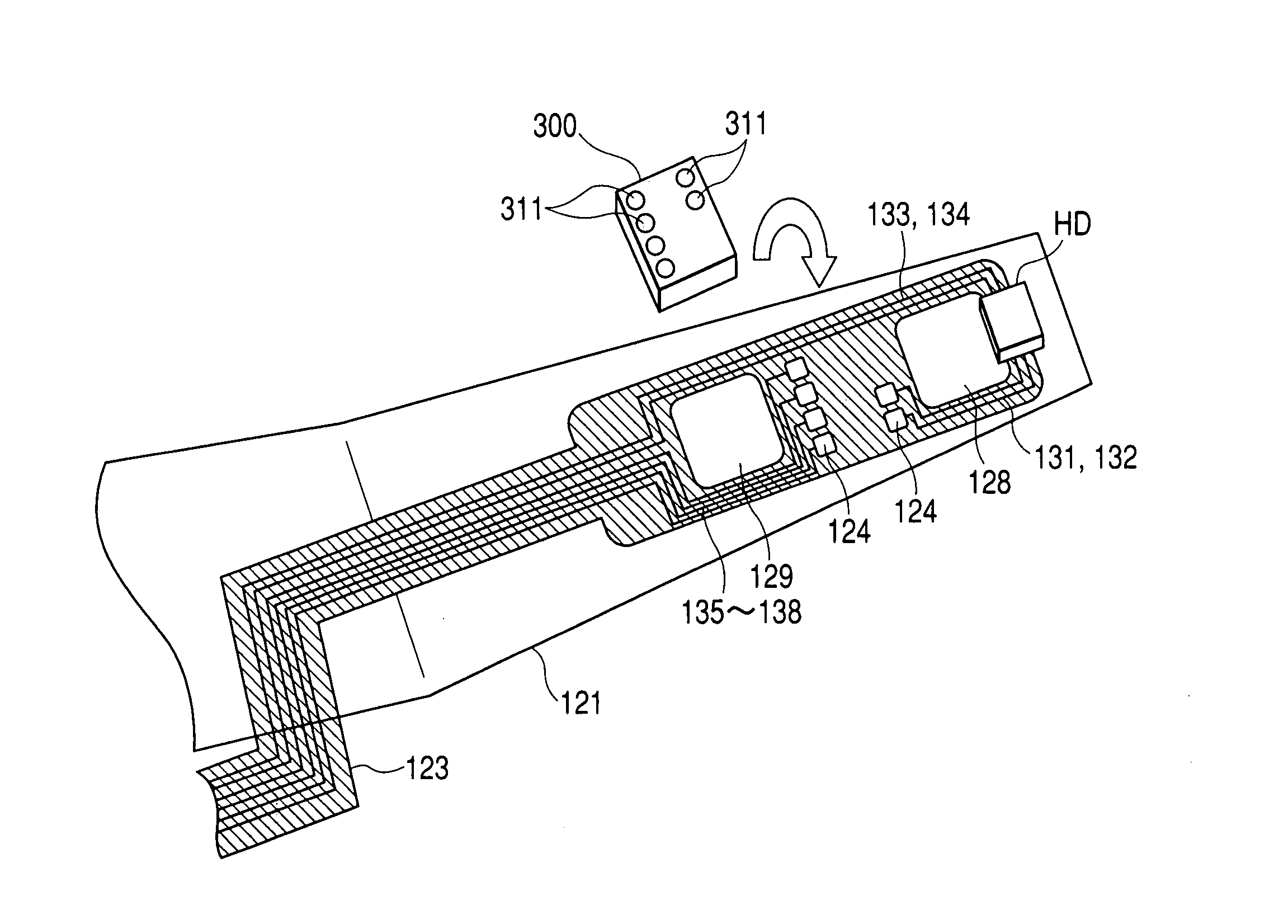
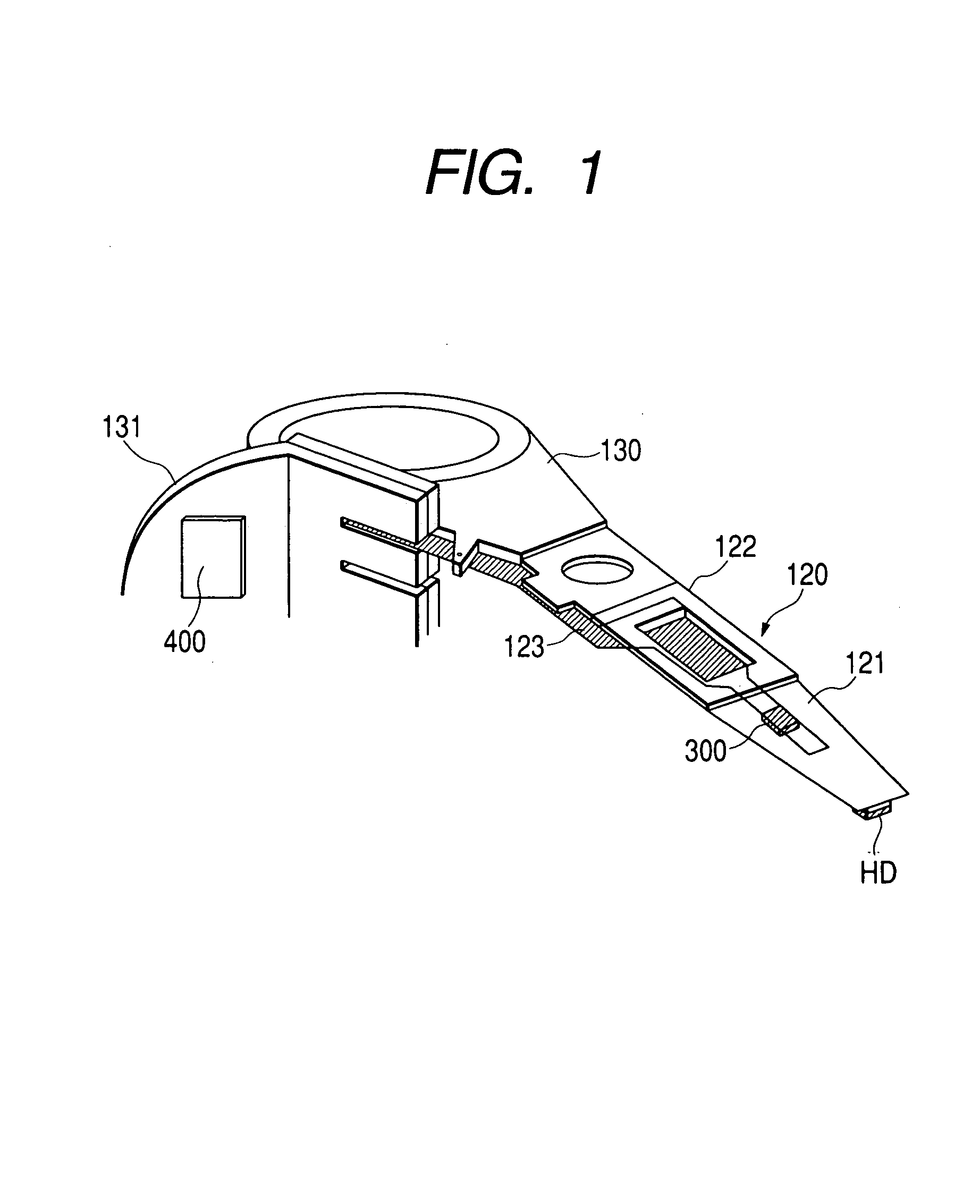
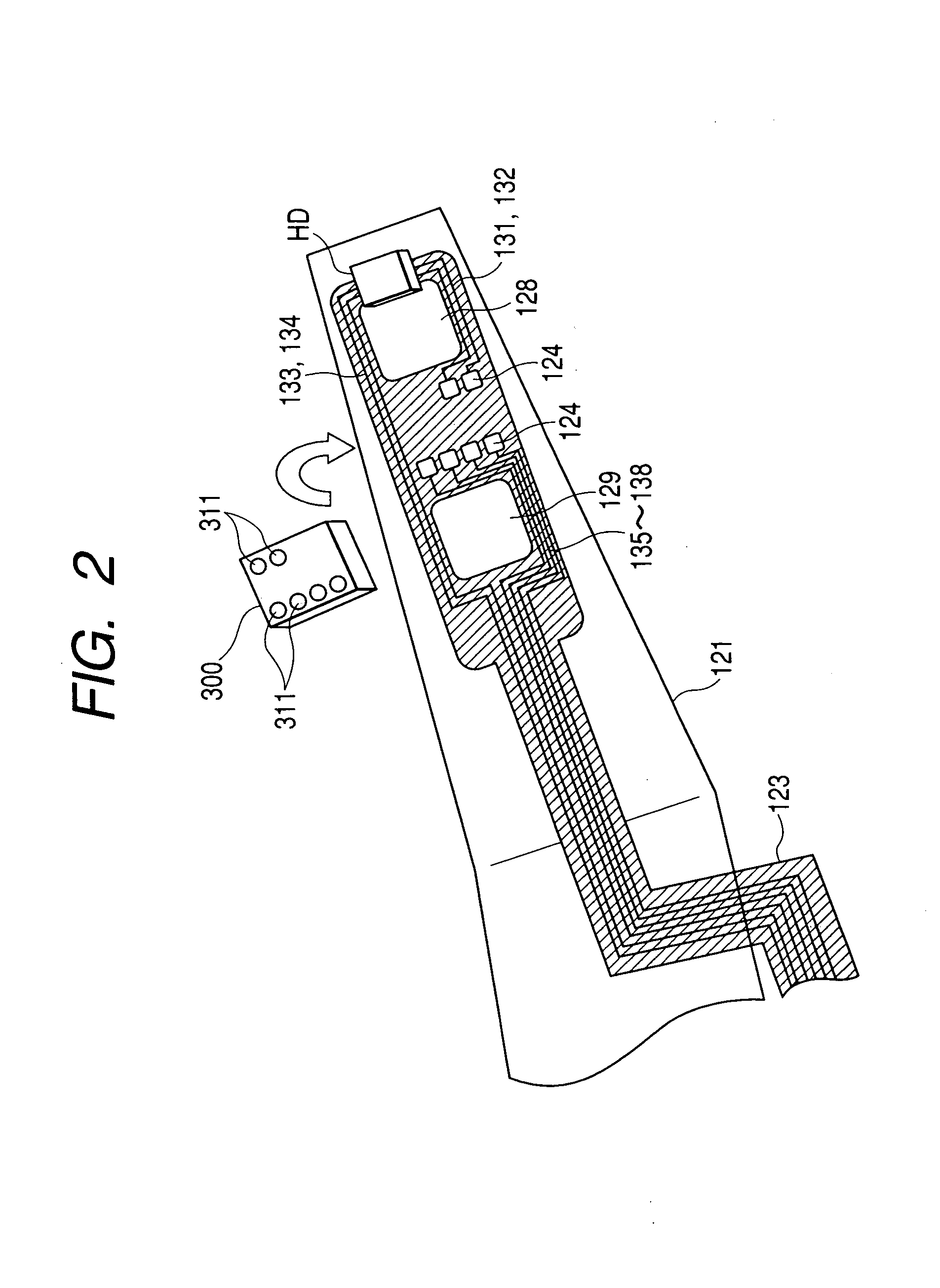
[0055]FIG. 1 illustrates a construction of an arm of the hard disk drive to which the present invention is applied. In FIG. 1, 120 denotes an arm having a magnetic head HD on the front, this arm is comprised of an elastic metal suspending part 121 and a base 122 to support the suspending part 121, and the magnetic head HD is mounted on the front of the suspending part 121, namely, on the underside of the end on the opposite side of the base 122. The base end of the base 122, namely, the end on the opposite side of the suspending part 121 is fastened to a carriage 130 as a moving means that moves the arm in the radial direction of a disk by a voice coil motor having a swingable structure, not illustrated. Here, FIG. 1 shows only one of the arms 120, but plural arms are provided in the same manner as in FIG. 23. Further, although not clear on the drawing, the magnetic head HD o...


PUM


Abstract

The storage media recording / writing system includes a media drive circuit, a head retaining means, a head moving means, a head drive circuit, a signal processing circuit, and a controller to control these. The head drive circuit possesses a first semiconductor integrated circuit having an amplifier that amplifies the read signal from the head, and a second semiconductor integrated circuit placed between the first semiconductor integrated circuit and the signal processing circuit, which has a circuit that receives write data from the signal processing circuit and generates a drive signal to drive a write head. Further, the first semiconductor integrated circuit is mounted on a part near the front of the head retaining means, and the second semiconductor integrated circuit is installed on the side of the moving means.

Description

[0001]This is a continuation application of U.S. Ser. No. 09 / 902,581, filed Jul. 12, 2001 now U.S. Pat. No. 6,762,896.BACKGROUND OF THE INVENTION[0002]The present invention relates to a storage media reading / writing system, specifically to a reading / writing semiconductor integrated circuit that amplifies a signal read from a head or drives the head by a write signal in the storage media reading / writing system of the magnetic recording system, which is a technique effective for use in a hard disk drive.[0003]Generally, the hard disk drive is provided on the side of a carriage 130, as shown in FIG. 23, with a reading / writing semiconductor integrated circuit (hereunder, referred to as read write IC) 220 that amplifies a signal read from a magnetic head or drives the magnetic head by a write signal to move an arm 120 furnished with the magnetic head for reading data stored in a magnetic disk 100 as storage media; and, the read write IC 220 and the magnetic head are connected usually wit...

Claims


Application Information

Patent Timeline
IPC IPC(8): G11B5/02G11B5/48G11B33/14G11B5/012G11B5/035G11B21/02G11B25/04G11B33/12
CPCG11B5/02G11B5/035G11B5/4833G11B5/484G11B5/012G11B33/121G11B33/122
Inventor YOSHIZAWA, HIROYASUKOBAYASHI, YOICHIROSHINOMIYA, TOSHIOFUJII, NORIYUKIYOSHINAGA, MASAKI
Owner HITACHI LTD
Why Eureka
Try Eureka