Decoupling element of deformable material in a power transmission system

a technology of deformation material and power transmission system, which is applied in the direction of winding motors, slip couplings, yielding couplings, etc., can solve the problems of unsatisfactory coating and molding operations in terms of cost and harm to the environment, -negligible extra costs, extra costs, etc., and achieves the effect of convenient assembly

Active Publication Date: 2007-07-17
HUTCHINSON SA
View PDF21 Cites 33 Cited by
  • Summary
  • Abstract
  • Description
  • Claims
  • Application Information

AI Technical Summary

Benefits of technology

[0014]Under such conditions, the work of the ring is performed by reducing the radial component of the compression which would otherwise become preponderant with increasing angular offset. A linear relationship between torque and offset is then ensured, which leads to constant stiffness over a large angular range, for example a range greater than ±9°, and thus to a narrow resonant band.
[0018]the projections are of constant or linearly varying profile so as to facilitate unmolding and assembly by self-centering when engaging the ring on the supports;
[0022]the ring is split to form an opening so as to make assembly easier during insertion of the hub by expanding the ring, and during its own insertion into the rim by compressing the ring, thereby compensating for play between the parts.

Problems solved by technology

That solution, as disclosed for example in patent EP 0 740 077 presents numerous drawbacks, and in particular:bonding requires coating and molding operations that are unsatisfactory in terms of cost and harm to the environment due to the use of adhesives and solvents;the inserts which are generally made of metal give rise to non-negligible extra cost;overmolding implies an additional swaging step to release differential stresses by radial deformation, and thus also leads to extra cost;force-fitting the inserts leads to stresses in the parts; andthe system cannot be disassembled.
That type of solution leads to non-linearity in the torque exerted as angular offset increases, and thus to non-linear stiffness, which is harmful to the filtering function.
However since the system is non-linear, its resonant bandwidth is very broad and filtering is not performed correctly.

Method used


Image

  • Decoupling element of deformable material in a power transmission system
  • Decoupling element of deformable material in a power transmission system
  • Decoupling element of deformable material in a power transmission system

Examples


Embodiment Construction

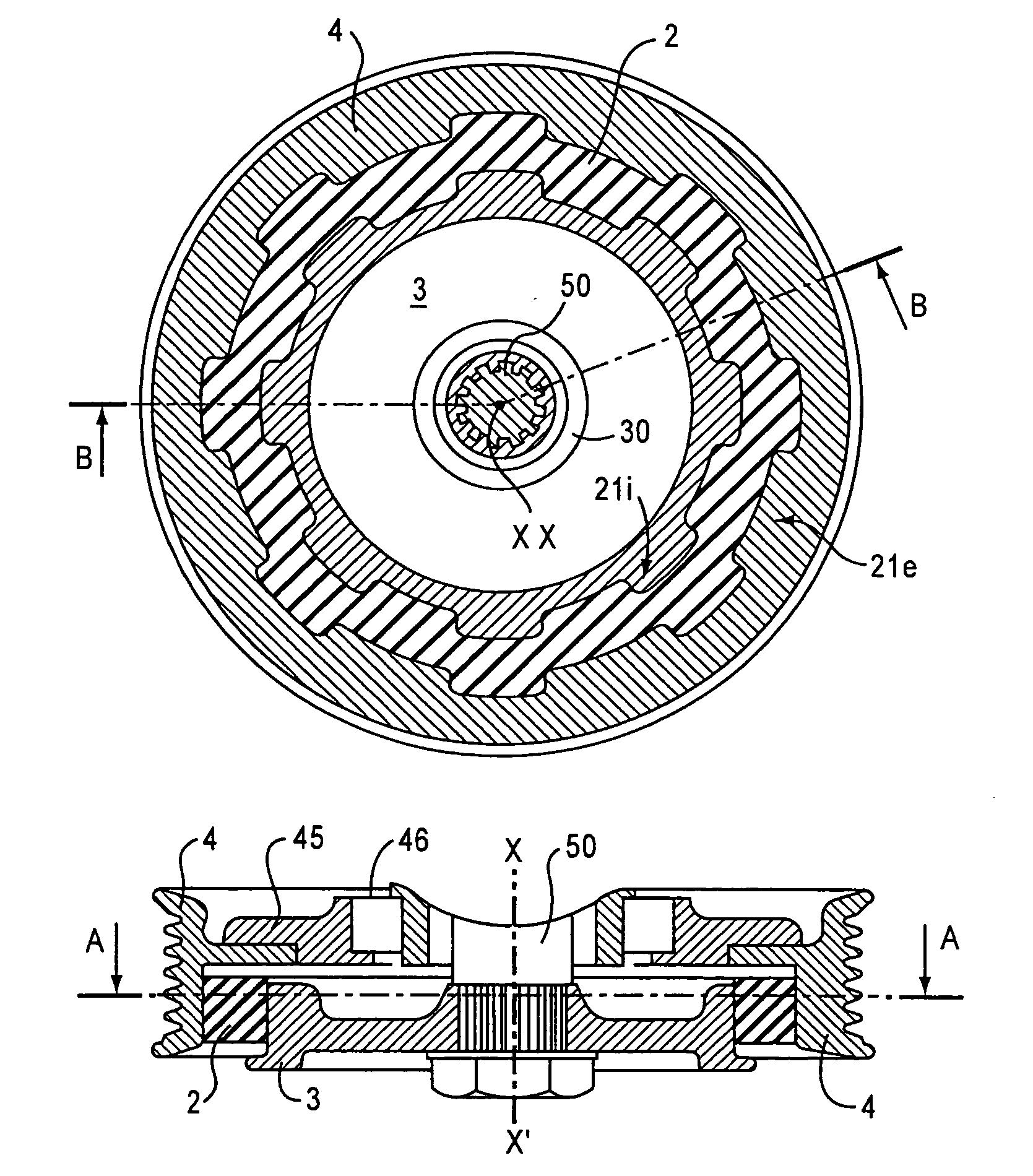
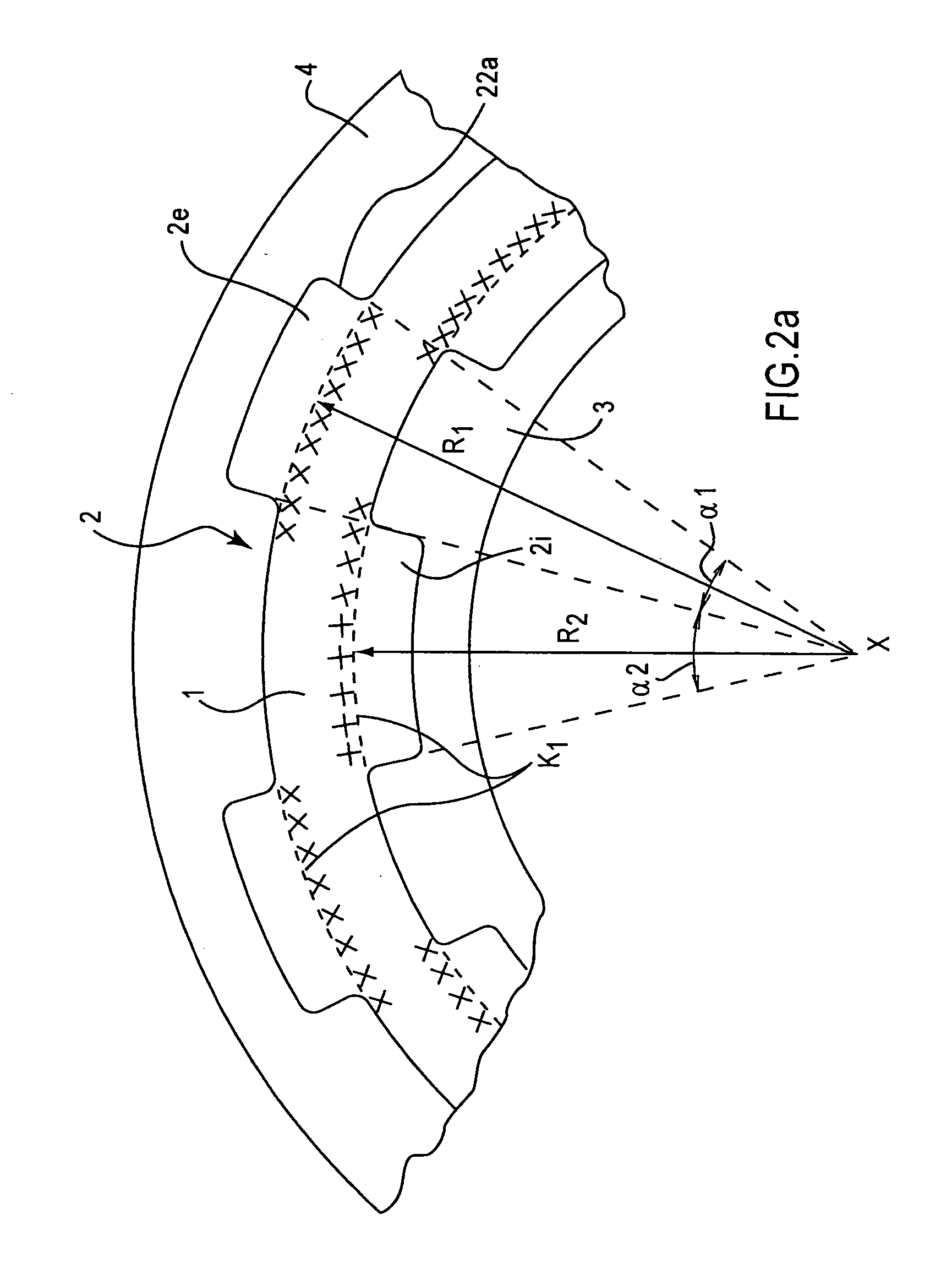
[0037]As shown diagrammatically in the fragmentary section of FIG. 2a, an example of a cylindrical decoupling ring 2 of the invention comprises a continuous annular central core 1 (outlined within the ring by dashed lines in the figure) and abrupt projections 2e, 2i extending radially from the side flanks 22a and projecting at right angles in this example.

[0038]The projections respectively referenced 2e and 2i are regularly distributed in alternation respectively on the outside face 21e and on the inside face 21i of the ring in particular in order to conserve good uniformity in mass distribution. A section of ring defined by a pair of successive projections, an inside projection and an outside projection, thus forms a basic pattern which is repeated around the ring so as to form cylindrical crenellated faces.

[0039]The ring meshes between two supports comprising a central hub 3 and a rim 4 presenting faces 31 and 41 that face the complementary faces 21i and 21i of the ring. The rim a...


PUM


Abstract

The invention seeks to improve the transfer function of drive devices such as pulleys and other coupling means, and it proposes creating zones of shear in the inserted deformable material forming a decoupling element. In an embodiment, the decoupling element is made in the form of a ring (2) presenting at least one meshing face (21e, 21i) complementary to a corresponding meshing face (31, 41) formed on the facing support (3, 4), the meshing projections (2e, 2i, 3e, 4i) engaging in one another to take up power transmission torque by working in shear by being blocked against each other during rotation. The invention is applicable to all drive devices including a filtering, damping, or absorbing element, e.g. for use in the automotive industry.

Description

BACKGROUND OF THE INVENTION[0001]The invention relates to a decoupling element of deformable material, such as rubber or elastomer, for a rotary drive device such as a pulley, a wheel, etc. in a power transmission system for a compressor, alternator, starter, or any other type of accessory that needs to be driven in rotation.[0002]As shown in the diagrammatic longitudinal and cross-section views of FIGS. 1a and 1b, pulleys or other rotary coupling means generally interpose a portion A of annular shape made of rubber having a section that is rectangular or shaped, between a rim B and a central hub C. By deforming in shear, between a rest position K0 and a position K in rotation, this piece allows a certain amount of angular offset to occur, thereby performing its decoupling function, in particular as a frequency filter and damper between the exciter (arrow E) and the response (arrow R). FIG. 1c shows a cross section similar to that of FIG. 1a with a link insert or friction layer D. T...

Claims


Application Information

Patent Timeline
Patent Type & Authority Patents(United States)
IPC IPC(8): F16D3/76F16D3/58F16D7/00
CPCF16D3/58F16D3/76F16D7/002Y10S474/902
Inventor KAMDEM, HENRIBOURDEAU, WILLY
Owner HUTCHINSON SA
Why Eureka
Try Eureka