Eureka AIR delivers breakthrough ideas for toughest innovation challenges, trusted by R&D personnel around the world.

Bladder with inverted edge seam and method of making the bladder

Inactive Publication Date: 2007-07-17
NIKE INC
View PDF179 Cites 104 Cited by
  • Summary
  • Abstract
  • Description
  • Claims
  • Application Information

AI Technical Summary

Benefits of technology

[0030]In accordance with one aspect of the present invention, a bladder is formed of multiple layers of barrier film to provide multiple pressurized layers of cushioning fluid or gas when the bladder is filled to provide layers of distinct cushioning properties. In a preferred embodiment, the distinct properties are caused by multiple pressurized layers of gas, wherein a multiple gas layer bladder enhances cushioning response by relying more on the response characteristics of the gas and reducing the amount of foam and the dependence on foam as a cushioning material.
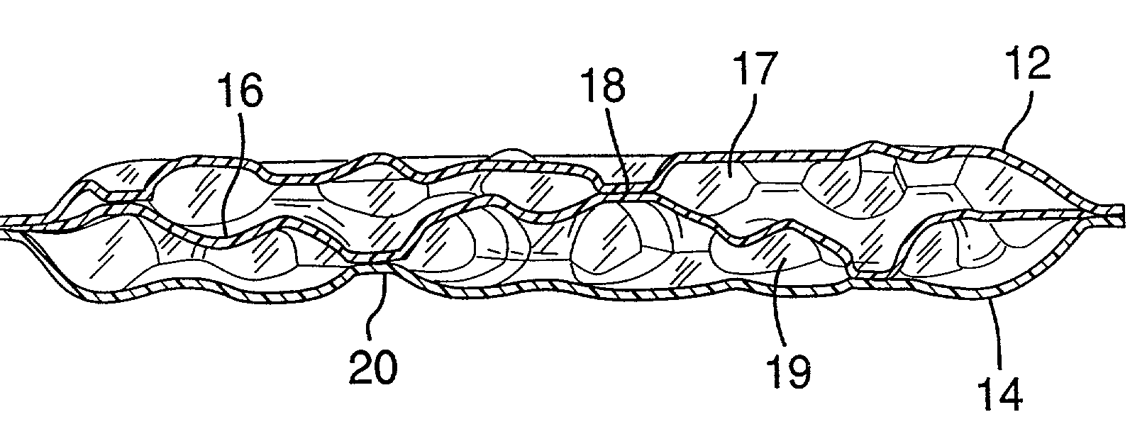
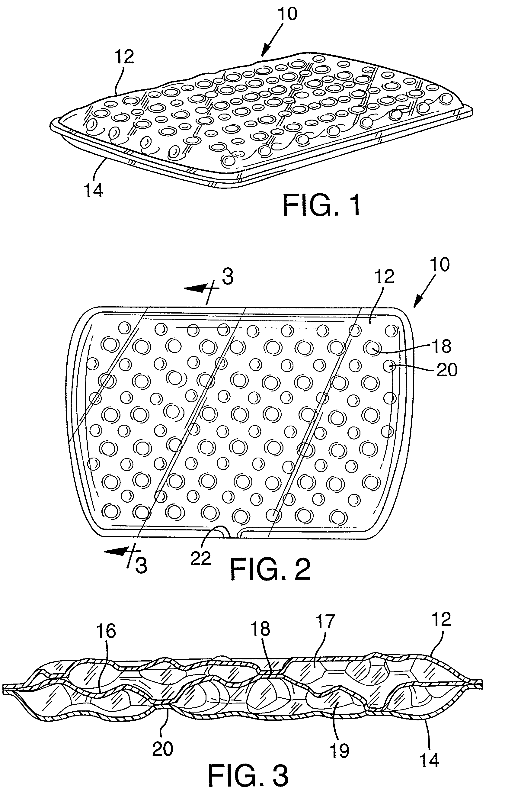
[0031]The most basic construction is a bladder formed of three barrier layers which forms two pressurized layers of gas. A three layer bladder comprises two outer layers sealed around a perimeter to form the envelope of the bladder and a middle layer which is attached to the outer layers and serves as a tensile element. The location of the connection sites of the middle layer to the outer layers determines the topography of the outer surface of the bladder. A middle layer also divides the interior of the bladder into at least two layers of fluid or gas. Additional layers of film between the outer envelope layers provide more layers of fluid or pressurized gas with the interior layers of film being attached to one another in ways to allow for further customization of the cushioning profile.
[0033]The inverted seam bladders can include separate top, bottom and sidewall pieces of barrier materials that are individually selected to provide increased durability, greater puncture resistance and localized stiffness, where needed, for enhanced cushioning, stability and longevity. The individual pieces of barrier material that form the sidewalls can be varied depending upon the needs of each portion of the sidewall. The bladder according to the present invention comprises a top sheet of a barrier material having a peripheral edge and, a bottom sheet of a barrier material being at least partially coextensive with the top sheet. The bladder also includes first and second sidewall elements comprised of the same or different barrier materials. The first sidewall element extends between the top and bottom sheets, and itself has top and bottom edges. The top edge of the first sidewall element is secured to the top sheet of barrier material proximate its peripheral edge, and bottom edge of the first sidewall element is secured to the second sidewall element. The opposite edge of the second sidewall element is secured to the bottom sheet of barrier material so that a fluid containing bladder is formed with two sidewall elements extending between the top and bottom sheets.
[0034]During the production of the bladder, the inverted seams are formed by arranging the barrier sheets and sidewalls pieces so they are at least partially coextensive and welding the two sidewall pieces of barrier material together at a location spaced inwardly from the peripheral welds that secure the two sidewall pieces to the top and bottom barrier sheets, respectively. After the sheets and sidewalls have been secured to each other so that a sealed inner chamber is formed, a cushioning fluid is introduced into the bladder. When more than four sheets of barrier material are used in forming a bladder, each inverted seam is formed by securing adjacent sidewall pieces of barrier material together at locations spaced inwardly from the welds that secure the sidewalls to the top and bottom barrier sheets. The inverted construction seams according to the present invention do not need to be treated with any finishing steps in order to improve their appearance or eliminate thick, rough edge. As a result, the costly production steps associated with finishing and reducing conventional construction seams are eliminated.
[0035]The present invention makes it possible for a manufacturer to aesthetically customize a bladder. The manufacturer can use different barrier materials for the top barrier sheet, bottom barrier sheet and portions of the sidewalls of the bladder. This allows the different parts of the bladder to be customized so the top and bottom sheets are not formed of the transparent sidewall material. The bladder can also be customized so the upper and lower pieces of a sidewall do not have to be formed of the same material. Materials can be used for the sidewalls that have a greater strength or thickness when compared to those used for the top and bottom pieces, or vice versa. Also, the materials used for the top and bottom sheets may not have to be as stiff or resistant to lateral stresses as are those used for the sidewalls.
[0036]The present invention also permits a manufacturer to customize a bladder so it has certain performance characteristics in selected areas without furnishing the entire bladder with these characteristics or the materials that provide them. For example, the sidewalls of a bladder according to the present invention can be customized by using a material with the same degree of vertical stiffness, resistance to vertical compression, as the pressurized chambers they define. These sidewalls complement the cushioning and stability of the chambers without requiring the top and bottom pieces to be as stiff as these sidewall pieces extending between them. The sidewalls or portions thereof can also be preformed to have different shapes and effects before being secured to the top and bottom pieces of the bladder.

Problems solved by technology

Although with recent developments in materials and manufacturing methods, fluid filled bladders have greatly improved in versatility, there remain problems associated with obtaining optimum cushioning performance and durability.
While EVA foam can easily be cut into desired shapes and contours, its cushioning characteristics are limited.
The major engineering problems associated with the design of air bladders formed of barrier layers include: (I) obtaining complex-curved, contoured shapes without the formation of deep peaks and valleys in the cross section which require filling in or moderating with foams or plates; (ii) ensuring that the means employed to give the air bladder its complex-curved, contoured shape does not significantly compromise the cushioning benefits of air; (iii) providing regionalized cushioning to an air bladder to account for differences in load corresponding to the anatomical topology of a human foot especially during high loads; (iv) designing air bladders which maximize the cushioning properties of air and are made entirely of flat barrier films; and (v) designing bladders that provide the advantages of complex-contoured shapes and regionalized cushioning and which can be integrated easily into existing midsole manufacturing methods.
The prior art is replete with attempts to address these difficulties, but have only solved one, two or even three of the above-described problems often presenting new obstacles in the process.
However, bladders with foam core tensile member have the disadvantage of unreliable bonding of the core to the barrier layers.
Another disadvantage of foam core bladders is that the foam core gives the bladder its shape and thus must necessarily function as a cushioning member which detracts from the superior cushioning properties of a gas alone.
Consequently, the reduction in the amount of gas in the bladder decreases the effectiveness of gas cushioning.
Even if a lower density foam is used, a significant amount of available volume is sacrificed which means that the deflection height of the bladder is reduced due to the presence of the foam, thus accelerating the effect of “bottoming out.” Bottoming out refers to the premature failure of a cushioning device to adequately decelerate an impact load.
Bottoming out is the point where the cushioning system is unable to compress any further and is a common failure in shoe soles comprised of foam.
The walls of individual cells constituting the foam structure abrade and tear as they move against one another and fail.
The breakdown of the foam exposes the wearer to greater shock forces.
One shortcoming of these bladders is that currently there is no known manufacturing method for making complex-curved, contoured shaped bladders using these fabric fiber tensile members.
Another disadvantage of fabric tensile members is the possibility of bottoming out.
Although the fabric fibers easily deflect under load and are individually quite small, the sheer number of them necessary to maintain the shape of the bladder means that under high loads, a significant amount of the total deflection capability of the air bladder is reduced by the volume of fibers inside the bladder and the bladder can bottom out.
One of the primary problems experienced with the fabric fibers is that these bladders are initially stiffer during initial loading than conventional gas filled bladders.
Further, no means are provided to cause the columns to flex in a predetermined fashion which would reduce fatigue failures.
Huang's columns are also prone to fatigue failure due to compression loads which force the columns to buckle and fold unpredictably.
Under cyclic compression loads, the buckling can lead to fatigue failure of the columns.
Another disadvantage of Reed is that because the third, middle sheet is attached with connection lines that extend across the entire width of the insole, all the chambers formed are independent of one another and must be inflated individually which is impractical for mass production.
The main disadvantage of this construction is that the ribs are vertically oriented and similar to the columns described in the patents to Huang and Moumdjian, would resist compression and interfere with and decrease the cushioning benefits of air.
There is, however, no provision for multiple layers of fluid in the bladder which could be inflated to different pressures providing improved cushioning characteristics and point of purchase feel.
Individual bladder components cannot be customized.
Unnecessarily thick top and bottom layers can detract from the overall flexibility of the bladder.
Conversely, if certain portions of the bladder, such as the top and bottom surfaces, needed to be made of a thicker material relative to the transparent sidewalls, the transparency and / or flexibility of the sidewalls may be compromised.
Preparing a bladder for being exposed along the length of a sole window can also include expensive and time consuming manufacturing steps.
The manufacturing steps taken to reduce the seam line increase the manufacturing time and cost of producing a bladder.
This simple profile seeks to balance the low-load-high-load criteria by a compromise to both since a simple cushioning profile provides generally uniform shock absorption and response characteristics along the entire device, but does not provide a complex cushioning profile which can be customized or regionalized to the loads realized at certain points along a bladder.
A problem with manufacturing complex, highly regionalized bladders of two films has been inordinate twisting of the fluid filled part.
A non-planar geometry is difficult to integrate into subsequent shoe making processes.
As discussed above, while the prior art has addressed some of these problems, they each have their disadvantages and fall short of a complete solution.

Method used


Image

  • Bladder with inverted edge seam and method of making the bladder
  • Bladder with inverted edge seam and method of making the bladder
  • Bladder with inverted edge seam and method of making the bladder

Examples


Embodiment Construction

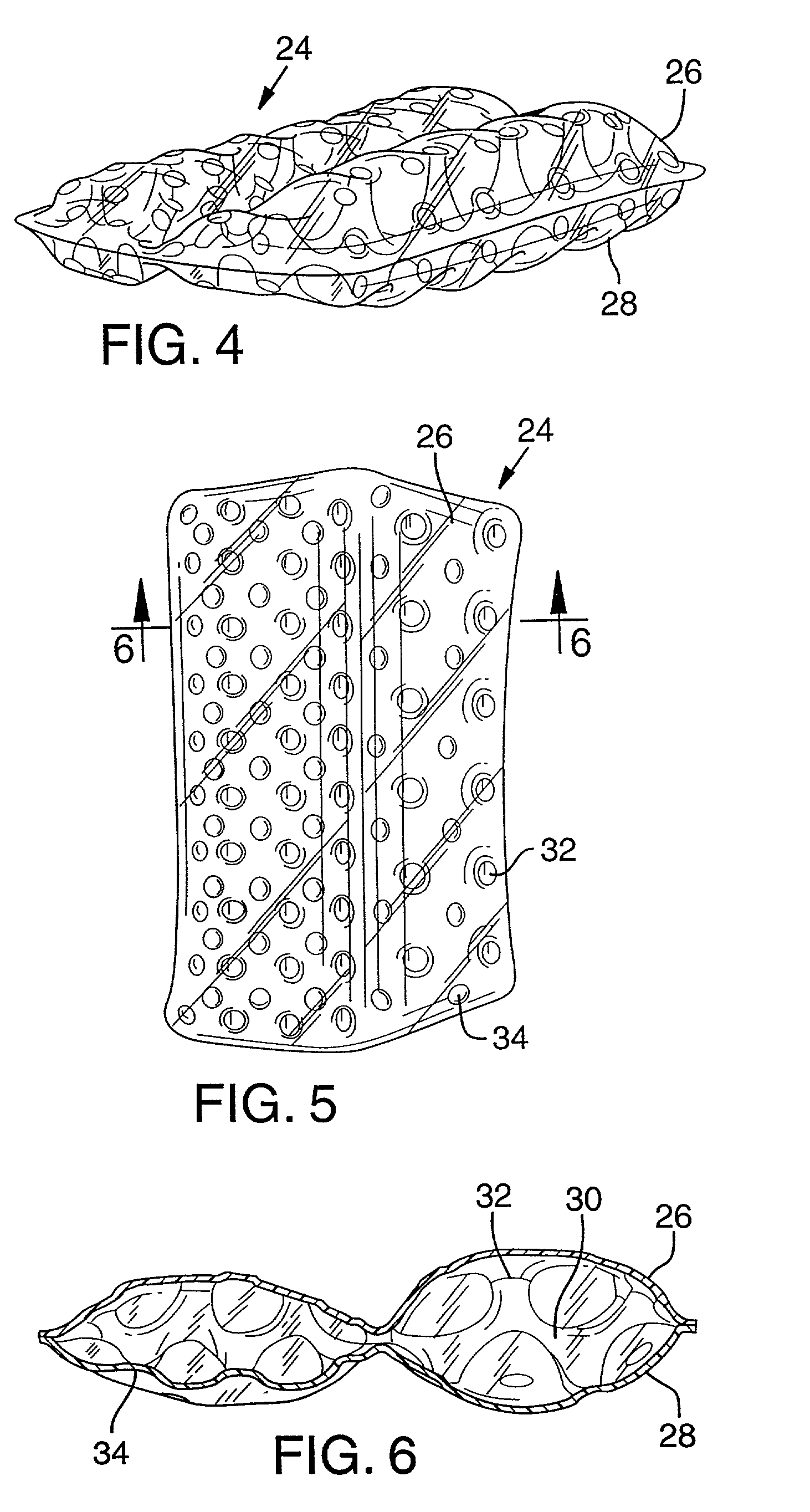
[0096]Reference is made to the figures which illustrate some permutations of preferred embodiments of multiple film layer bladders. Due to the complex geometries of multiple film layer bladders, for the sake of clarity, in some instances the perspective views of the bladders are illustrated as if the outer film layers are opaque with the inner construction shown in cross section. It is understood that the film layers may be transparent, tinted or opaque, or some combination of films of different appearance. The term “connection site” is used throughout the application to refer broadly to attachment locations between any of the film layers. A convention employed in the drawings is to show connection sites by outline only or as an outline surrounded by arcs. The sites with arcs depict a connection between an inner film layer and the outer film layer closest to the viewer. The sites showing only the connection outline depict a connection between two inner film layers, or between an inn...


PUM

PropertyMeasurementUnit
Pressureaaaaaaaaaa
Tensile propertiesaaaaaaaaaa
Shapeaaaaaaaaaa

Abstract

The invention is a bladder formed of multiple layers of barrier film to provide multiple pressurized layers of cushioning fluid or gas when the bladder is filled. The sidewalls of the bladder can be constructed with an inverted seam construction to eliminate finishing steps in the manufacture of cushioning bladders and alternatively to provide a clean, seamless appearance along the side walls. The inverted seam can be formed by attaching the peripheral edges of inner barrier layers to the outer barrier layers adjacent a weld between inner barrier layers to provide an inside-out inverted seam appearance. An inverted seam can also be formed by providing separate sidewall elements attached to the barrier layers of the bladder to provide a seam displaced from the center of the sidewall.

Description

[0001]This is a divisional application that claims priority under 35 U.S.C. §120 to U.S. patent application Ser. No. 09 / 526,863, filed Mar. 16, 2000 now U.S. Pat. No. 6,402,879.FIELD OF THE INVENTION[0002]The present invention relates to an improved cushioning member for a shoe, and more particularly to a fluid filled bladder having multiple layers of chambers with an inverted edge seam and a method of forming an improved cushioning member with inverted seam lines along its sidewalls.BACKGROUND OF THE INVENTION[0003]Considerable work has been done to improve the construction of cushioning members which utilize fluid filled bladders such as those used in shoe soles. Although with recent developments in materials and manufacturing methods, fluid filled bladders have greatly improved in versatility, there remain problems associated with obtaining optimum cushioning performance and durability. Fluid filled bladder members are commonly referred to as “air bladders,” and the fluid is gene...

Claims


Application Information

Patent Timeline
IPC IPC(8): B29D22/00B29D23/00B32B1/08A43B13/20A43B21/28
CPCA43B13/20A43B21/285Y10T428/1352Y10T156/1016Y10T428/231A63B59/0092A63B60/54B29D22/02A43B13/00A43D27/00
Inventor TAWNEY, JOHN C.HERRIDGE, DAVID B.
Owner NIKE INC
Why Eureka
Eureka Blog
Learn More