Intravascular stent with extendible end rings

a stent and end-ring technology, applied in the field of intravascular stents, can solve the problems of stent end restenosis, development of restenosis, and injury to the arterial wall by non-working length, and achieve the effects of reducing the likelihood of peri-stent end restenosis, facilitating delivery, and being highly flexibl

Inactive Publication Date: 2007-07-24
ABBOTT CARDIOVASCULAR
View PDF10 Cites 48 Cited by
  • Summary
  • Abstract
  • Description
  • Claims
  • Application Information

AI Technical Summary

Benefits of technology

[0004]The present invention is directed to an intravascular stent that has a pattern or configuration that permits one or more end rings to extend longitudinally as the stent is expanded radially. The extension of the end rings in the longitudinal direction will permit drug delivery from a drug coating on the end rings to extend beyond the balloon working length. By delivering a therapeutic drug beyond the balloon working length, the drug coated stent and end rings will reduce the likelihood of the development of peri-stent restenosis. The stent also is highly flexible along its longitudinal axis to facilitate delivery through tortuous body lumens, but which is stiff and stable enough radially in its expanded condition to maintain the patency of a body lumen such as an artery when the stent is implanted therein.

Problems solved by technology

While some of these stents are flexible and have the appropriate radial rigidity needed to hold open a vessel or artery, there typically is a tradeoff between flexibility and radial strength and the ability to tightly compress or crimp the stent onto a catheter so that it does not move relative to the catheter or dislodge prematurely prior to controlled implantation in a vessel.
One problem being encountered with stent, including these drug coated stents, is that restenosis can sometimes occur at the stent ends, both distally and proximally of the implanted stent.
While various theories exist as to the reasons for the development of restenosis at the stent ends, one important factor appears to be injury to the arterial wall by the non-working length of the balloon.
In other words, that portion of the balloon that extends beyond the stent will expand into the arterial wall and cause stretching or other injury that will eventually lead to the development of restenosis.
As a result, the likelihood of the development of restenosis beyond the ends of the stent is much greater since the therapeutic drug does not treat that injured area.

Method used


Image

  • Intravascular stent with extendible end rings
  • Intravascular stent with extendible end rings
  • Intravascular stent with extendible end rings

Examples


Embodiment Construction

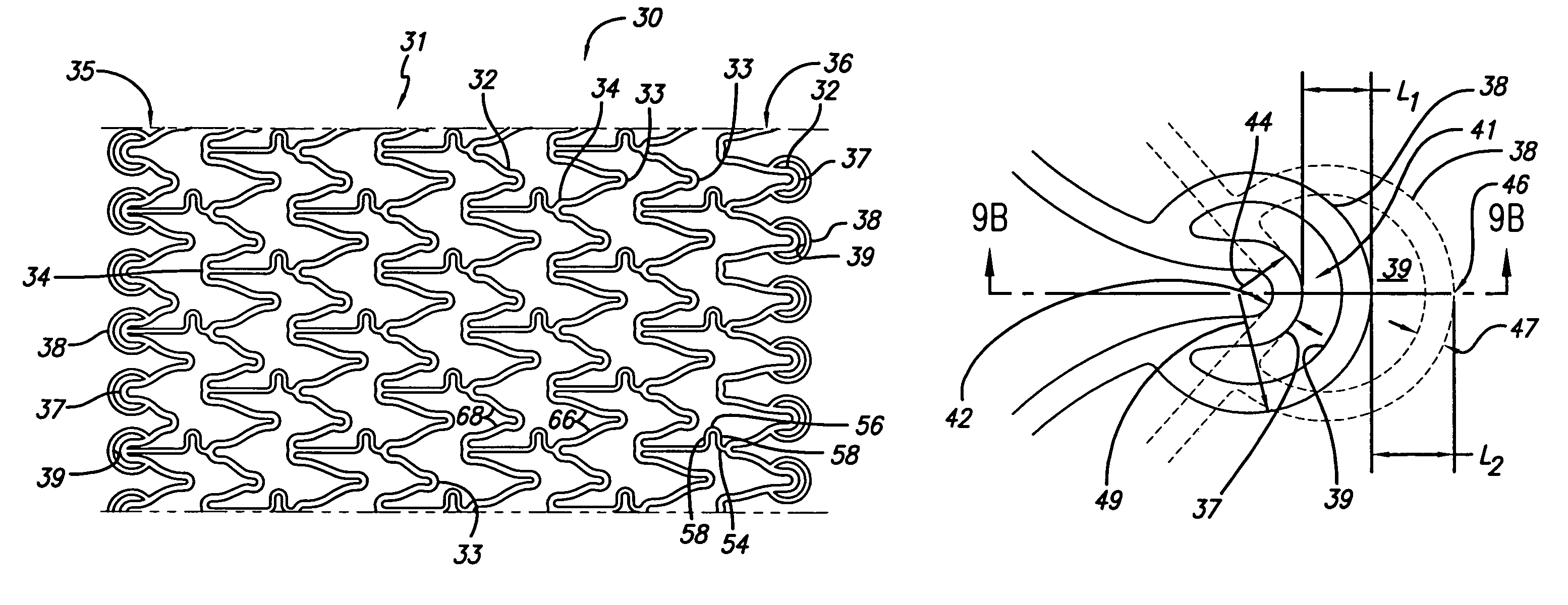
[0040]The present invention stent improves on existing stents by providing a longitudinally flexible stent having a uniquely designed pattern of expandable cylindrical rings with stent end rings that lengthen as the rings expand radially outwardly. A distal end ring lengthens distally in a longitudinal direction and a proximal end ring extends and lengthens longitudinally in the proximal direction as the stent expands due to the unique and novel twin peak design. The stent can be drug coated so that the therapeutic drug is delivered by the extended end rings to reduce the likelihood of the development of peri-stent restenosis. In addition to providing longitudinal flexibility, the stent of the present invention also provides radial rigidity and a high degree of scaffolding of a vessel wall, such as a coronary artery.

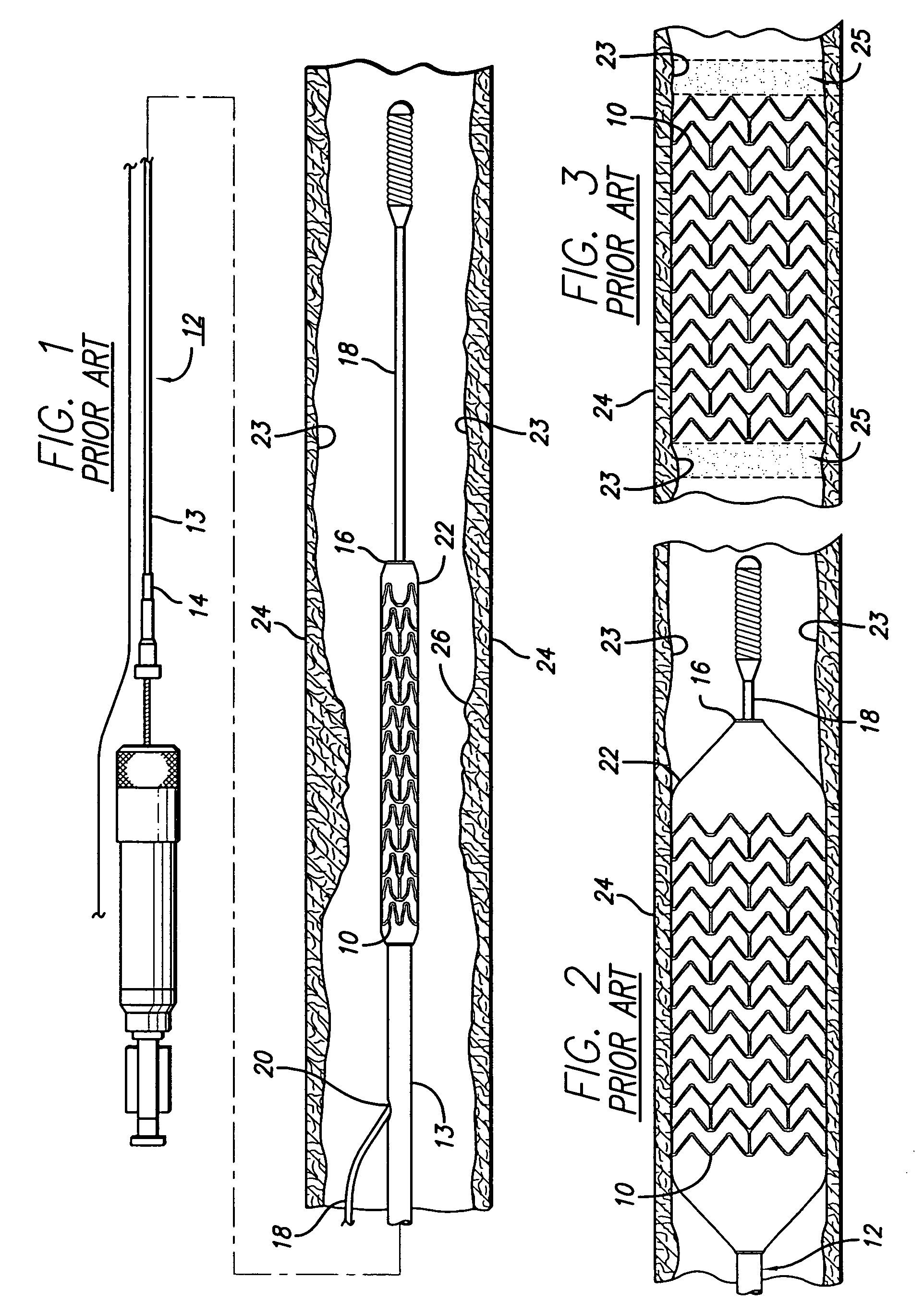
[0041]Turning to the drawings, FIG. 1 depicts a prior art stent 10 mounted on a conventional catheter assembly 12 which is used to deliver the stent and implant it in a ...


PUM


Abstract

An expandable stent for implanting in a body lumen, such as a coronary artery, peripheral artery, or other body lumen includes cylindrical rings connected by undulating links. The stent has a high degree of flexibility in the longitudinal direction, yet has adequate vessel wall coverage and radial strength sufficient to hold open an artery or other body lumen. The distal and proximal end ring have peaks that extend longitudinally when the stent is radially expanded. The end ring extensions reduce the likelihood of the development of peri-stent restenosis.

Description

BACKGROUND OF THE INVENTION[0001]The invention relates to vascular repair devices, and in particular intravascular stents, which are adapted to be implanted into a patient's body lumen, such as a blood vessel or coronary artery, to maintain the patency thereof. Stents are particularly useful in the treatment of atherosclerotic stenosis in arteries and blood vessels.[0002]Stents are generally tubular-shaped devices which function to hold open a segment of a blood vessel or other body lumen such as a coronary artery. They also are suitable for use to support and hold back a dissected arterial lining that can occlude the fluid passageway. At present, there are numerous commercial stents being marketed throughout the world. For example, the prior art stents depicted in FIGS. 1-5 have multiple cylindrical rings connected by one or more undulating links. While some of these stents are flexible and have the appropriate radial rigidity needed to hold open a vessel or artery, there typically...

Claims


Application Information

Patent Timeline
Patent Type & Authority Patents(United States)
IPC IPC(8): A61F2/06A61M29/02A61F2/00A61F2/90
CPCA61F2/915A61F2002/91508A61F2002/91516A61F2230/0054A61F2002/91533A61F2002/91575A61F2250/0036A61F2002/91525
Inventor PIENKNAGURA, CARLA ROSA
Owner ABBOTT CARDIOVASCULAR
Why Eureka
Try Eureka