
Frequency compensation architecture for stable high frequency operation

a high-frequency operation and frequency compensation technology, applied in differential amplifiers, amplifiers with semiconductor devices/discharge tubes, amplifier details, etc., can solve the problems of circuit b>10/b> being insufficient for desirable operation, circuit b>10/b> is still limited, and the system bandwidth is still limited

Inactive Publication Date: 2007-07-24
MARVELL INT LTD
View PDF3 Cites 16 Cited by
  • Summary
  • Abstract
  • Description
  • Claims
  • Application Information

AI Technical Summary

Benefits of technology

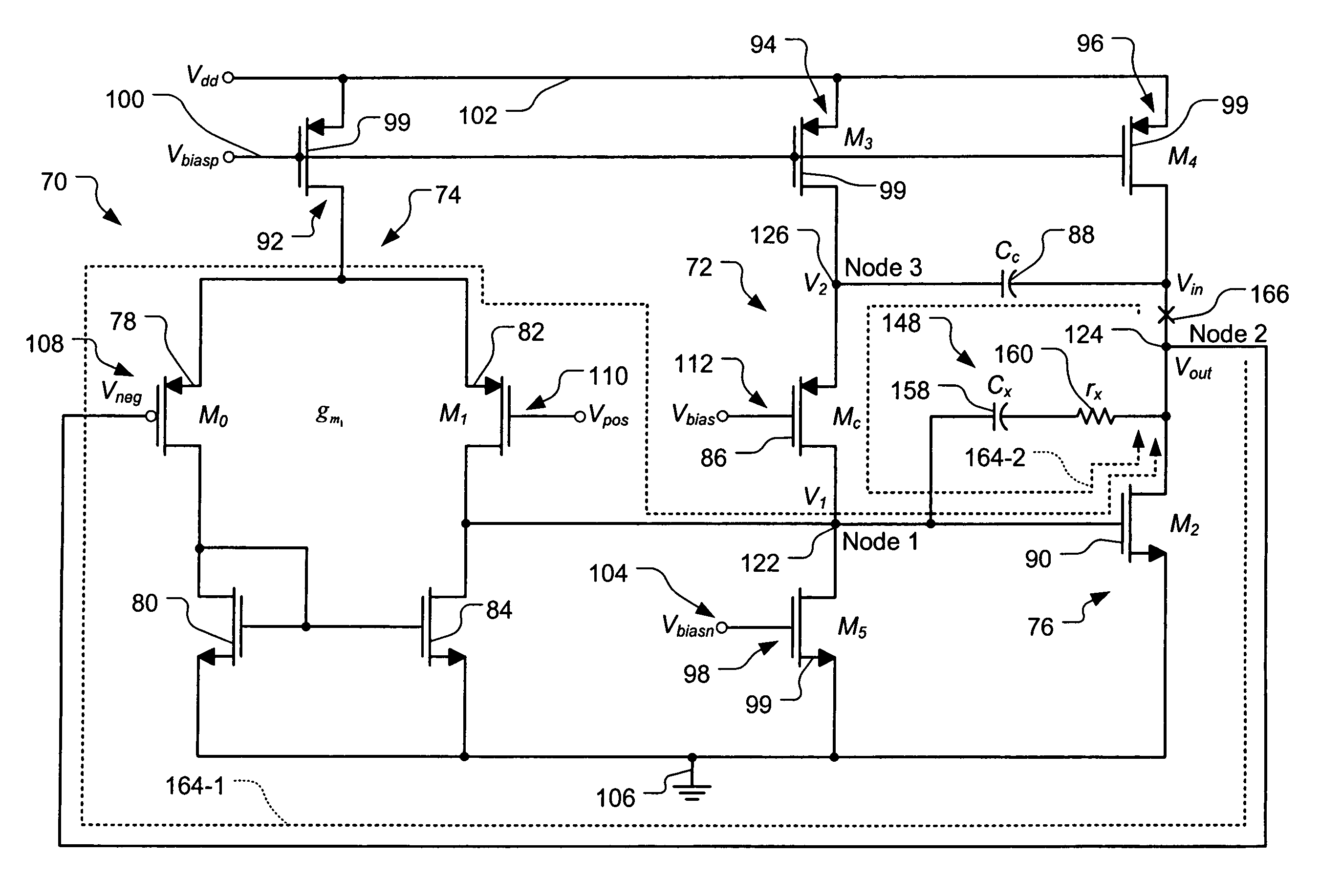
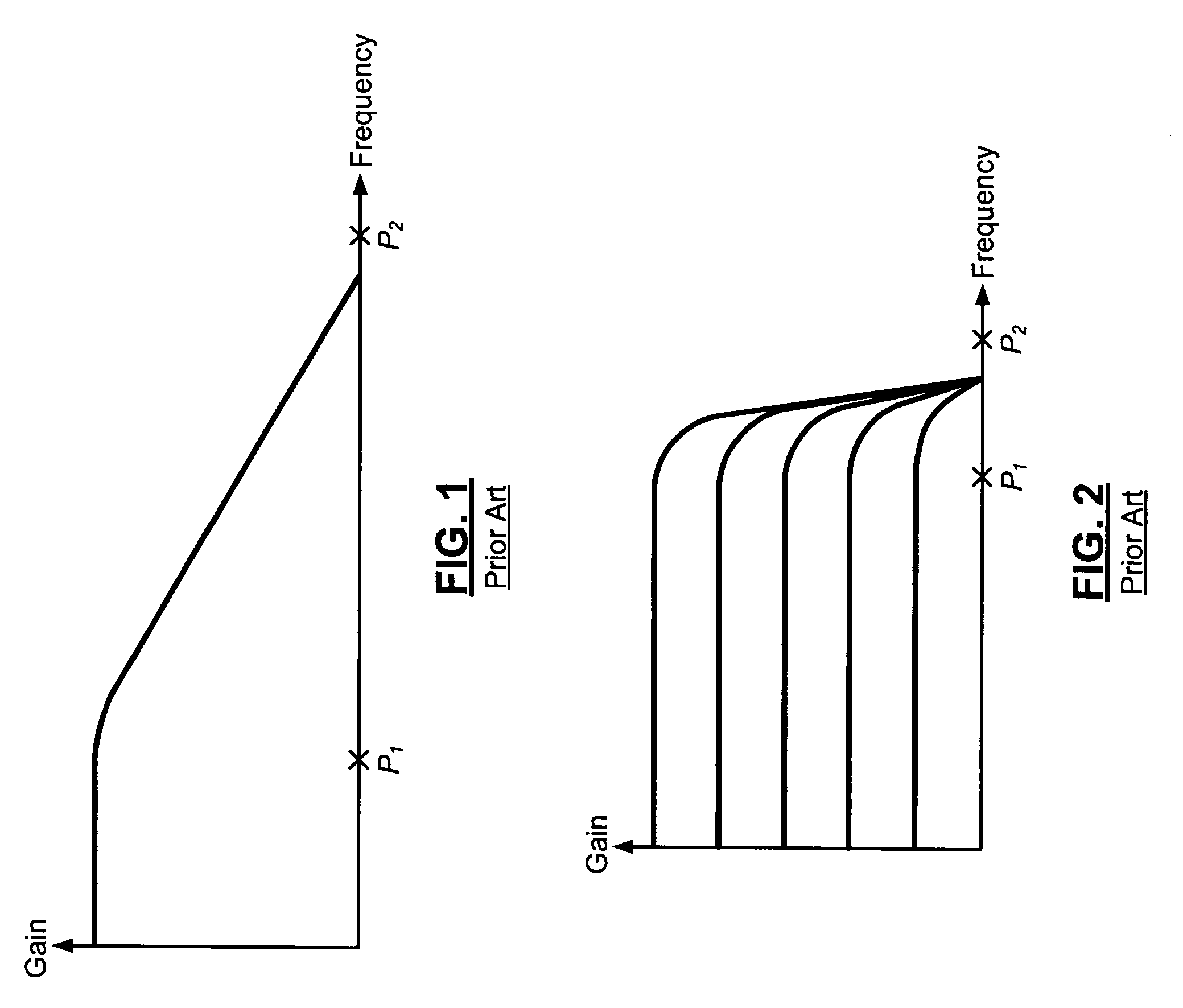
[0020]In yet other features, a feedback loop has an open loop response with first and second poles that are located below a crossover frequency. The Miller compensation circuit increases a frequency difference between the first and second poles. The feedback loop includes third and fourth poles and a second zero that are located above the crossover frequency. The open loop response further includes a zero that is located below the crossover frequency. The Miller compensation circuit adjusts a frequency of one of the poles so that the zero cancels an effect of the pole on the open loop response.

Problems solved by technology

At some point, this will cause oscillation.
At some point, this too will cause oscillation.
While the dominant pole may be moved to a lower frequency using this approach, bandwidth of the system is still limited.
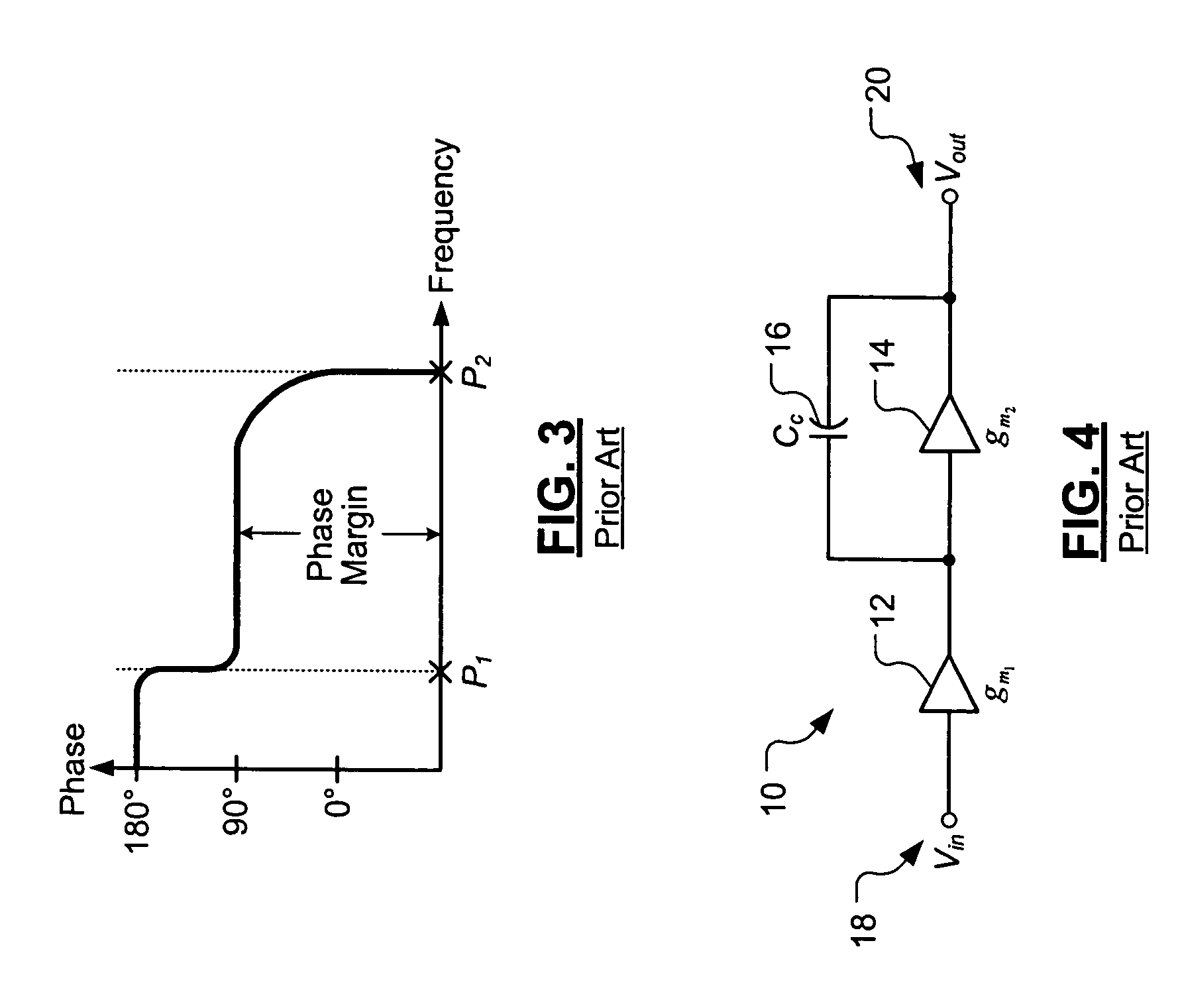
The poles that exist at the two high impedance nodes are close in frequency, which creates instability in the circuit 10.
Therefore, if a good PSRR is required, the circuit 10 is insufficient for desirable operation.
However, during high frequency operations, the loop gain drops.
Eventually, the loop gain diminishes, and the feedback loop is no longer able to correct disturbances at the output of the circuit 10.
However, noise from the reference potential no longer directly couples to the output of the circuit 60.

Method used


Image

  • Frequency compensation architecture for stable high frequency operation
  • Frequency compensation architecture for stable high frequency operation
  • Frequency compensation architecture for stable high frequency operation

Examples


Embodiment Construction

[0044]The following description of the preferred embodiment(s) is merely exemplary in nature and is in no way intended to limit the invention, its application, or uses. For purposes of clarity, the same reference numbers will be used in the drawings to identify similar elements. As used herein, the term module refers to an application specific integrated circuit (ASIC), an electronic circuit, a processor (shared, dedicated, or group) and memory that execute one or more software or firmware programs, a combinational logic circuit, and / or other suitable components that provide the described functionality.

[0045]The most commonly used and well-known frequency compensation method for two-stage operational amplifiers (op-amps) is Miller Compensation. However, Miller Compensation circuits have a poor AC power supply rejection (PSRR) to the power rails. In 1983, Bhupendra K. Ahuja invented an improved frequency compensation technique called Ahuja compensation. By using this compensation met...


PUM


Abstract

An operational transconductance amplifier includes a first amplifier circuit that generates a first bias. A second amplifier circuit receives the first bias and generates a feedback signal. The first amplifier circuit also receives the feedback signal. A Miller compensation circuit receives the feedback signal and generates a second bias. An Ahuja compensation circuit receives the first and second biases and the feedback signal and generates a third bias. The second amplifier circuit receives the third bias. A feedback loop has an open loop response with first and second poles and a zero that are located below a crossover frequency. The Miller compensation circuit increases a frequency difference between the first and second poles. The Miller compensation circuit also adjusts a frequency of one of the poles so that the zero cancels an effect of the pole on the open loop response.

Description

CROSS-REFERENCE TO RELATED APPLICATIONS[0001]This application claims the benefit of U.S. Provisional Application No. 60 / 650,320, filed on Feb. 4, 2005, which is hereby incorporated by reference in its entirety.FIELD OF THE INVENTION[0002]The present invention relates to frequency compensation circuits, and more particularly to frequency compensation circuits for operational transconductance amplifiers.BACKGROUND OF THE INVENTION[0003]The most relevant characteristics of an amplifier circuit are usually gain and bandwidth. In order to derive the bandwidth, an open loop response technique is used. The technique of looking at the open loop response provides information relating to the bandwidth and maximum achievable bandwidth of an amplifier circuit.[0004]The DC gain of the open loop response is determined by opening the feedback loop and attaching a voltage source to an input side of the opened feedback loop. The output voltage is sensed at an output side of the opened feedback loop....

Claims


Application Information

Patent Timeline
Patent Type & Authority Patents(United States)
IPC IPC(8): H03F3/45
CPCH03F1/086H03F3/45183
Inventor LI, YING TIANZHANG, YAYUE
Owner MARVELL INT LTD
Learn More