Passive subharmonic mixer design

a subharmonic mixer and subharmonic technology, applied in the field of radio receivers, can solve the problems of large power consumption and general complexity of the superheterodyne receiver, the direct conversion design, and the problem of large power consumption to maintain linear operation, etc., to achieve the effect of reducing local oscillator radiation, low supply voltage and low power dissipation

Inactive Publication Date: 2007-07-24
SHEN REALTY
View PDF5 Cites 25 Cited by
  • Summary
  • Abstract
  • Description
  • Claims
  • Application Information

AI Technical Summary

Benefits of technology

[0015]Accordingly, it is a primary object of the present invention to provide a passive subharmonic mixer design that can reduce local oscillator radiation, operate at low supply voltages, work with low power dissipation, and achieve high linearity. The new mixer can be used in a direct conversion or low IF receiver architecture to increased integration and decreased power consumption without the operational problems associated with previous r

Problems solved by technology

Moreover, the necessity for mixer and local oscillator circuits operating at high frequencies contributes greatly to the power consumption and general complexity of the superheterodyne receiver.
In particular, the high-frequency analog mixers require a large amount of power to maintain linear operation.
Although many variations of the superheterodyne design exist, they all share the limitations of the particular design just described.
The direct-conversion design, however, h

Method used


Image

  • Passive subharmonic mixer design
  • Passive subharmonic mixer design
  • Passive subharmonic mixer design

Examples


Embodiment Construction

[0022]FIG. 4 is a block diagram of a passive mixer known as prior art [3]. It consists of RF inputs, 101 and 102, that are connect to four MOS switches, 107-110, with gates driven by the local oscillator positive and negative differential phases, 103 and 104. The load capacitor 111 is used to filter the high frequency noise of the system. The local oscillator signal, 103 and 104, inverts the phase of the RF input, 101 and 102, on every half cycle, thus producing the mixing function between the RF input and the local oscillator input. Because the switches are passive components and do not dissipate power, the passive mixer has advantages compared to an active mixer with reduce power and improved linearity.

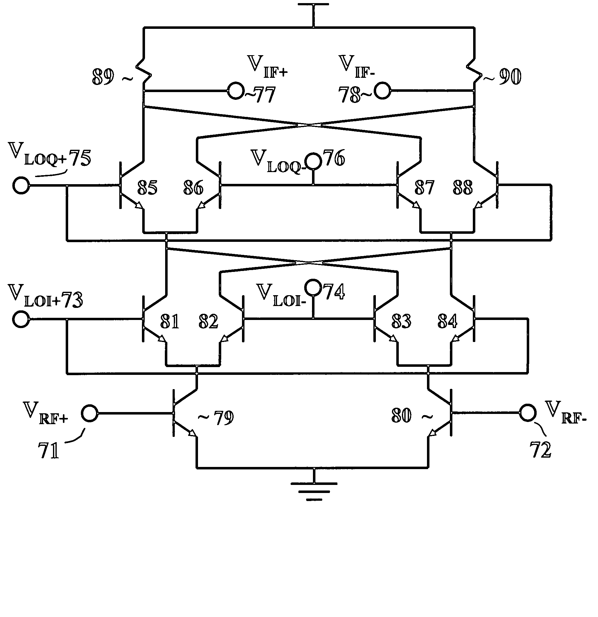
[0023]FIG. 5 is a schematic of a passive subharmonic mixer constructed in accordance with the principles of the present invention. This embodiment is for a local oscillator running at one half the mixing frequency, and thus requires differential in-phase 123 and 124 and quadrature-p...


PUM


Abstract

A mixer design is described that permits greater integration on standard silicon chips with an improvement in power and linearity compared to previous mixer designs, enabling low-power, high performance RF reception.

Description

[0001]This application is based on the provisional application No. 60 / 431,979 filed on Dec. 10, 2002 and application Ser. No. 10 / 729,638 filed on Dec. 5, 2003REFERENCES[0002][1] Sheng, et al., “A Wide-Bandwidth Si / SiGE Direct Conversion HBT Sub-Harmonic Mixer / Downconverter,”IEEE Journal of Solid-State Circuits, vol. 36, no. 9, September, 2000, pp. 1329-1337.[0003][2] U.S. Pat. No. 6,370,372, Apr. 9, 2002, Molnar et al.[0004][3] Crols, et al., “A 1.5 GHz Highly Linear CMOS Downconversion Mixer,”IEEE Journal of Solid-State Circuits, vol. 30, no. 7, July 1995, pp. 736-742.BACKGROUND[0005]1. Technical Field of Invention[0006]The present invention relates to radio receivers and methods for the reception of RF (radio frequency) communication signals in a highly integrated receiver.[0007]2. Background of The Invention and Discussion of Prior Art[0008]At the present time, the vast majority of RF communication receivers are of the superheterodyne type. This type of receiver uses one or more ...

Claims


Application Information

Patent Timeline
IPC IPC(8): H04B1/28H03D7/14
CPCH03D7/1433H03D7/1441H03D7/1458H03D7/1466H03D7/1475H03D7/165
Inventor SHEN, DAVID H.
Owner SHEN REALTY
Why Eureka
Try Eureka