Laser projection display and illumination device with MEMS scanning mirror for indoor and outdoor applications

a technology of scanning mirror and projection display, which is applied in the direction of display means, color television details, instruments, etc., can solve the problems of large electrical power consumption of display systems, and bulky construction of display systems, so as to avoid jitter of projected images

Inactive Publication Date: 2007-08-07
ADVANCED NUMICRO SYST
View PDF19 Cites 90 Cited by
  • Summary
  • Abstract
  • Description
  • Claims
  • Application Information

AI Technical Summary

Benefits of technology

[0006]In one embodiment of the invention, a compact, low power projection display system is proved to produce a bright image viewable in both indoor and outdoor environments. The projection display system includes a light source unit that generates monochrome light beams, an optical modulation unit that modulates the monochrome light beams to desired hues and tones, an optical synthesizing device that combines the monochrome light beams into one single light beam, a reflecting mirror unit for scanning the one single light beam to project a two-dimensional image, and an image processing unit that decodes a composite image signal to control signals for the optical modulation unit and the reflecting mirror unit. The projection display apparatus system further includes a sensing unit that generates a feedback signal of the speed and the position of the reflecting mirror unit in order to maintain the synchronization of light radiation and to avoid jitter of the projected image.
[0007]The light source unit may be solid state including laser diodes, either edge emitting type or surface emitting type, diode pumped solid state frequency doubled (DPSSFD) laser, or high brightness light emitting diodes. The light source unit may generate light beams in red, green and blue colors for creating a color image, or a single selected color for a monochrome image. The solid state light source unit may emit in free space or be guided in optical fibers for easy assembly.

Problems solved by technology

These display systems typically consume substantial electrical power and are bulky in construction.
In addition, some of these display systems cannot display images with sufficient brightness to be visible indoor under illumination or outdoor under daylight.
The lifetime of these bulbs presents a challenge against the constant use of these systems to display images.
These systems are also inherently cumbersome and expensive because they utilize mechanical deflectors, polygonal mirror, and galvanometer mirror.

Method used


Image

  • Laser projection display and illumination device with MEMS scanning mirror for indoor and outdoor applications
  • Laser projection display and illumination device with MEMS scanning mirror for indoor and outdoor applications
  • Laser projection display and illumination device with MEMS scanning mirror for indoor and outdoor applications

Examples


Embodiment Construction

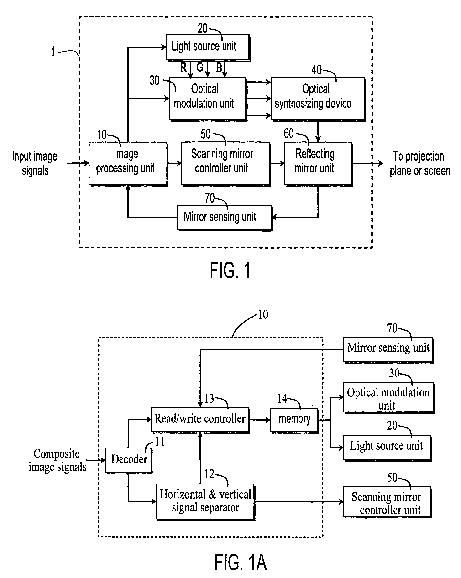
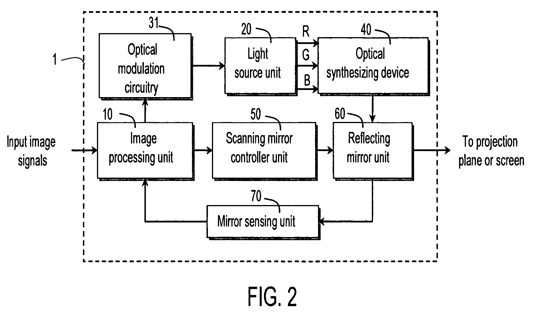
[0029]FIG. 1 illustrates a projection display system 1 in one embodiment of the invention. Projection display system 1 includes an image processing unit 10, a light source unit 20, an optical modulation unit 30, an optical synthesizing device 40, a scanning mirror controller unit 50, a reflecting mirror unit 60, and a mirror sensing unit 70.

[0030]FIG. 1A illustrates image processing unit 10 in one embodiment. Image processing unit 10 includes (1) a decoder 11 for dividing a composite image signal into a composite synchronous signal, a red signal, a green signal, and a blue signal, (2) a signal separator 12 for separating the composite synchronous signal into a horizontal synchronization signal and a vertical synchronization signal, (3) a read / write controller 13 for controlling the light source unit 20 and synchronizing the vertical and the horizontal synchronization signals with the position and speed of reflecting mirror unit 60, and (4) a memory 14 for buffering the red, green, a...


PUM


Abstract

A projection display system includes a light source emitting a light beam, and a reflecting mirror system for scanning the light beam over an image to illuminate the image. The light source can be solid state such as a laser diode. The reflecting mirror system can be one or more MEMS scanning mirrors that rotate to raster scan the light beam over the image. The image can be an advertisement located on a wall, a screen, a sign, or a billboard. The image can also be a semi-transparent image that is projected onto a medium to produce a larger image.

Description

CROSS REFERENCE TO RELATED APPLICATIONS[0001]This application is a continuation of U.S. patent application Ser. No. 10 / 613,397, filed on Jul. 3, 2003, now abandoned, and incorporated herein by reference.FIELD OF INVENTION[0002]The invention relates to an image projection apparatus employing micro-electro-mechanical system (MEMS) scanning mirrors and laser light sources.DESCRIPTION OF RELATED ART[0003]Various display systems have been developed for illuminating graphics for indoor and outdoor advertisement and entertainment. Some examples of these display systems include illuminated billboards, light-emitting diode (LED) displays, neon light signs, and liquid crystal flat-panels. These display systems typically consume substantial electrical power and are bulky in construction. Thus, substantial efforts are spent to transport, set up, power, and maintain these display systems. In addition, some of these display systems cannot display images with sufficient brightness to be visible in...

Claims


Application Information

Patent Timeline
Patent Type & Authority Patents(United States)
IPC IPC(8): G03B21/14
CPCG03B21/28H04N9/3129G02B26/101Y10S362/812
Inventor FU, YEE-CHUNG
Owner ADVANCED NUMICRO SYST
Why Eureka
Try Eureka