
Apparatus to produce acoustic cavitation in a liquid insonification medium

a liquid insonification medium and acoustic cavitation technology, applied in the direction of mechanical vibration separation, cleaning using liquids, instruments, etc., can solve the problems of small bubbles, increased bubble response, and increased bubble growth due to rectifying,

Inactive Publication Date: 2007-08-07
OVIVO SWITZERLAND AG
View PDF11 Cites 5 Cited by
  • Summary
  • Abstract
  • Description
  • Claims
  • Application Information

AI Technical Summary

Benefits of technology

"The invention is a device that creates vacuous cavitation in a liquid medium using a single transducer. The device produces an acoustic field with multiple high and low frequency components using a bipolar inharmonic tone burst signal. The device can be controlled to vary the duty cycle, amplitude, and frequency of the signal. The invention can be used to induce cavitation in a liquid insonification medium and can be used to treat objects within the medium. The technical effects of the invention include the ability to create vacuous cavitation in a liquid medium using a single transducer and controlling the acoustic field produced using a bipolar inharmonic tone burst signal."

Problems solved by technology

Consequently, there is a net diffusion of the gas into the bubble from the surrounding liquid over a complete cycle, which causes bubble growth due to rectified diffusion.
Surface tension effects are, however, significant for small bubbles.
Bubble response becomes increasingly vigorous at the resonance radius, and is limited by damping mechanisms in the bubble environment—e.g., viscous damping, acoustic radiation damping, and thermal damping.
Free bubbles, however, do not last long in a body of water.
It is very difficult to cavitate clean liquids (Greenspan and Tschiegg, 1967).
Observed strengths (thresholds) in practice, however, are very much lower, rarely exceeding a few bars for reasonably clean liquids.
Over-pressuring the liquid for sufficient duration prior to insonification can force the meniscus further into the crevice thereby causing full wetting of the crevice, which then gives rise to increased cavitation thresholds.
Even so, when these applications were extended to semiconductor applications, cavitation was deemed detrimental to the delicate wafer surfaces, which spawned the use of megasonic cleaning to avoid cavitation (e.g. U.S. Pat. No. 4,854,337 to Bunkenburg et al., 1989; U.S. Pat. No. 4,979,994 to Dussault et al., 1990; U.S. Pat. No. 5,247,954 to Grant et al., 1993; and U.S. Pat. No. 5,355,048 to Estes, 1994) thus teaching the use of frequencies in the range of high kilohertz or low megahertz (typically 1 MHz).
Planar piezoelectric transducers cannot generate very high pressure amplitudes with moderate power inputs.
With increased power, however, cavitation might occur on the surface of the transducer crystal itself which will cause destruction of the crystal.
Even so, high intensity acoustic waves invariably become non-linear because of inherent properties of the propagation medium.
Without the presence of appropriate nuclei the tensile peak is ineffective in causing cavitation.
It is known in the art that transducers generating high pressure amplitudes at high frequencies are technologically unfeasible (high frequency resonant crystals are necessarily thin and cannot support stresses needed for generating high pressures), and yet to generate cavitation at high acoustic frequencies, the pressure amplitudes necessary are excessive.
To bring about cavitation in ultra clean hosts, especially at high frequencies, is almost impossible primarily because the acoustic drivers, the piezoelectric transducers used to generate cavitation cannot be made to generate high pressure amplitude sound waves at high frequencies.
Being gas-filled these long-lived bubbles cannot sufficiently implode to create high energy density points in the medium, and are thus ineffective to bring about the effects of ACIM described herein.
It is known in physics of liquids that free bubbles in a liquid are unstable and do not survive for any significant duration after their creation.
Not all liquid borne particles are capable of supporting such partially wetted crevices, particularly, smooth spherical particles cannot harbor such gas-filled cavities.

Method used


Image

  • Apparatus to produce acoustic cavitation in a liquid insonification medium
  • Apparatus to produce acoustic cavitation in a liquid insonification medium
  • Apparatus to produce acoustic cavitation in a liquid insonification medium

Examples


Embodiment Construction

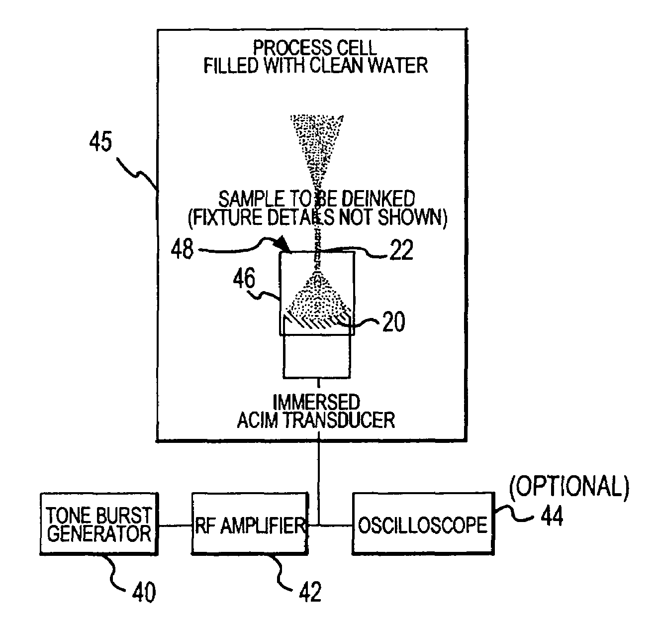
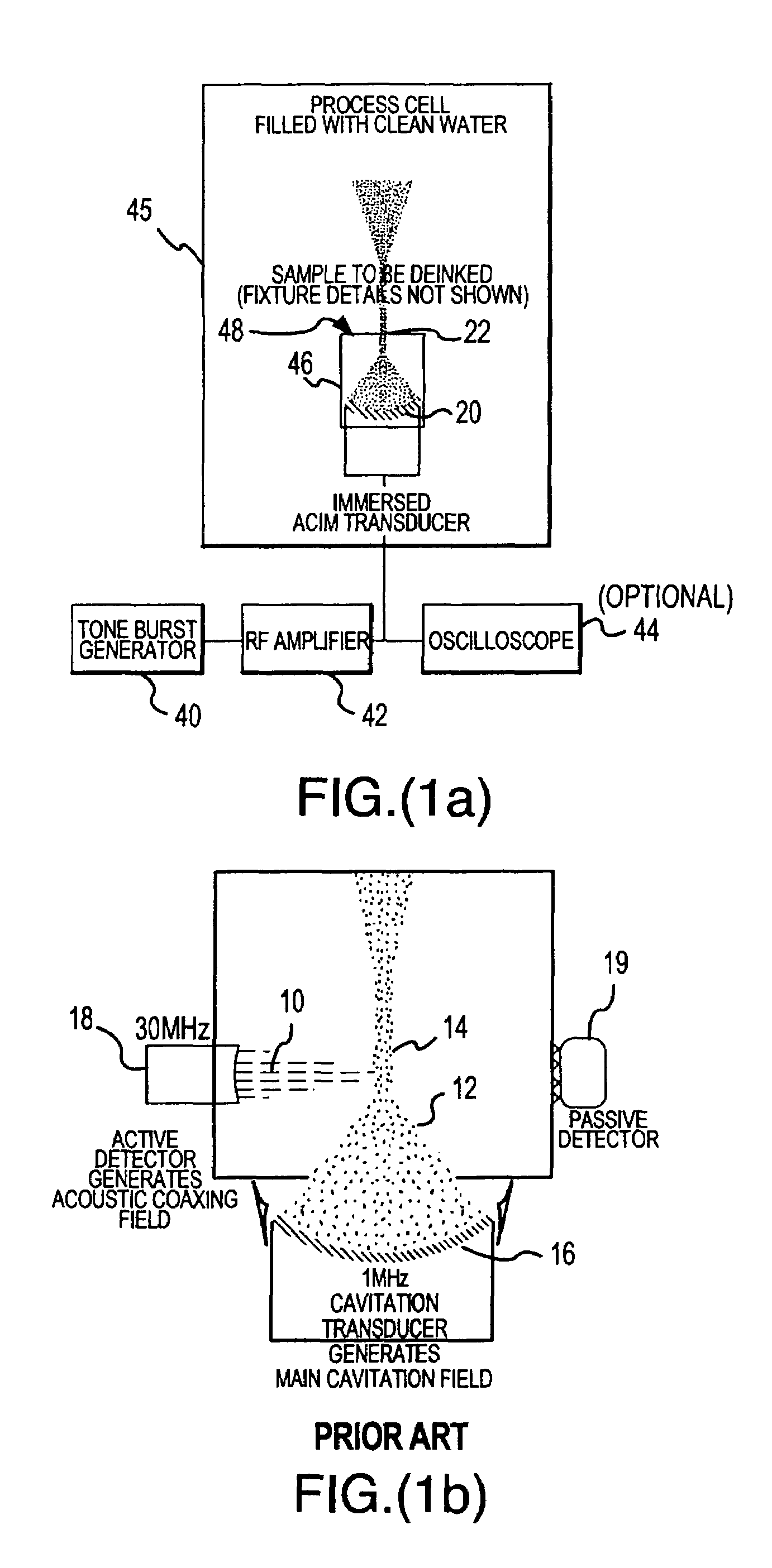
[0047]Acoustic coaxing induced microcavitation (ACIM) methods and apparatuses described herein may be used to control microcavitation at point solid boundaries of an object or workpiece to perform work on the object; examine free bubbles in a fluid or liquid for testing or measuring; induce or assist a chemical reaction; or perform other scientific, industrial, or medical tasks. ACIM tools may be constructed to perform abrasion, cutting, drilling, or other action with respect to a variety of organic and inorganic materials, including tissue and bone.

[0048]Controlled ACIM enables one to control the onset, evolution, and intensity of acoustic microcavitation stemming from the creation of new nuclei or the presence of available cavitation nuclei in a liquid medium, such as de-ionized or tap water. Such nuclei may come from free bubbles or from liquid-borne solid particulates with crevice-like features that stabilize significant gas pockets. Suspended particulates may include sub-micron...


PUM


Abstract

An apparatus to produce acoustic cavitation by controlling cavitation events in a liquid insonification medium utilizing a waveform to excite a transducer with a series of bipolar inharmonic tone bursts having medium recovery intervals between respective bursts so that the medium repeatedly recovers from cavitation events between bursts. The apparatus may be used to clean a semiconductor wafer, to de-coat a painted surface having, to induce a chemical reaction, and / or to provide recycled paper made from inked paper de-inked by cavitation. Cavitation events are generated using a transducer and a waveform generator, e.g., square wave tone bursts, to excite the transducer with a signal controlled in frequency, burst repetition rate, duty-cycle and / or amplitude, e.g., utilizing bursts having a frequency between 500 KHz and 10 MHz, and a duty cycle between 0.1% and 70%.

Description

CROSS-REFERENCE TO RELATED PATENTS AND PATENT APPLICATIONS[0001]This invention is a continuation of commonly-owned, U.S. application Ser. No. 10 / 153,903 filed May 24, 2002 now abandoned, which is a continuation of U.S. application Ser. No. 09 / 488,574 filed Jan. 21, 2000 (now U.S. Pat. No. 6,395,096) claiming the benefit of provisional application Ser. No. 60 / 116,651 entitled “Single Transducer System for Submicron Particle Detection and / or Removal” filed Jan. 21, 1999[0002]This invention is also related to U.S. Pat. Nos. 5,594,165 and 5,681,396, which disclose microcavitation for submicron particle detection and removal.BACKGROUND OF THE INVENTION[0003]This invention relates to acoustic cavitation, but more specifically, to an apparatus to produce acoustic cavitation using a single transducer to subject an article or component thereof to microcavitation events generated in a liquid insonification medium.[0004]Acoustic microcavitation, which is the inducement of micron or sub-micron ...

Claims


Application Information

Patent Timeline
Patent Type & Authority Patents(United States)
IPC IPC(8): H02N2/00B08B3/12
CPCB06B1/0215B06B1/0603B06B1/067B08B3/12G10K11/006G10K11/08G10K15/043B06B2201/71Y10S134/902
Inventor MADANSHETTY, SAMEER I.
Owner OVIVO SWITZERLAND AG
Learn More