Method and apparatus for performing second harmonic optical coherence tomography

a second harmonic optical coherence and tomography technology, applied in the field of optical coherence tomography, can solve the problems of small changes in sample linear scattering properties, difficult to detect, and difficult to change tissue morphology and refractive index between normal and diseased tissues, so as to reduce the amount of reflected light

Active Publication Date: 2007-08-14
RGT UNIV OF CALIFORNIA
View PDF2 Cites 31 Cited by
  • Summary
  • Abstract
  • Description
  • Claims
  • Application Information

AI Technical Summary

Benefits of technology

[0009]A pair of prisms is disposed in the optical path of the signal arm or reference arm to compensate for the group-velocity dispersion of the fundamental and harmonic waves or group velocity mismatch in the signal arm and reference arm, thus enabling simultaneous observation of SH-OCT interference signals and conventional OCT interference signals.
[0012]In the embodiment where the light source comprises a mode-locked laser the apparatus further comprises an optical isolator for preventing back-scattered light from entering the light source and interfering with mode locking.
[0016]A dichroic mirror and translation stage coupled to the mirror serve as an optical terminus in the reference arm to act as an optical delay line. The dichroic mirror differentially reflects the fundamental and second harmonic frequency of the light signal in the reference arm to reduce the amount of reflected light at the fundamental frequency, which is transmitted toward the nonlinear crystal.

Problems solved by technology

In many instances such as pathological processes in tissue, changes in sample linear scattering properties are small and difficult to measure.
For example, many cancers originate in the epithelium that has a thickness suitable for OCT imaging, but in their early stages when these cancers are developing through cell dysplasia, changes in tissue morphology and refractive index between normal and diseased tissues are very small and difficult to detect.

Method used


Image

  • Method and apparatus for performing second harmonic optical coherence tomography
  • Method and apparatus for performing second harmonic optical coherence tomography
  • Method and apparatus for performing second harmonic optical coherence tomography

Examples


Embodiment Construction

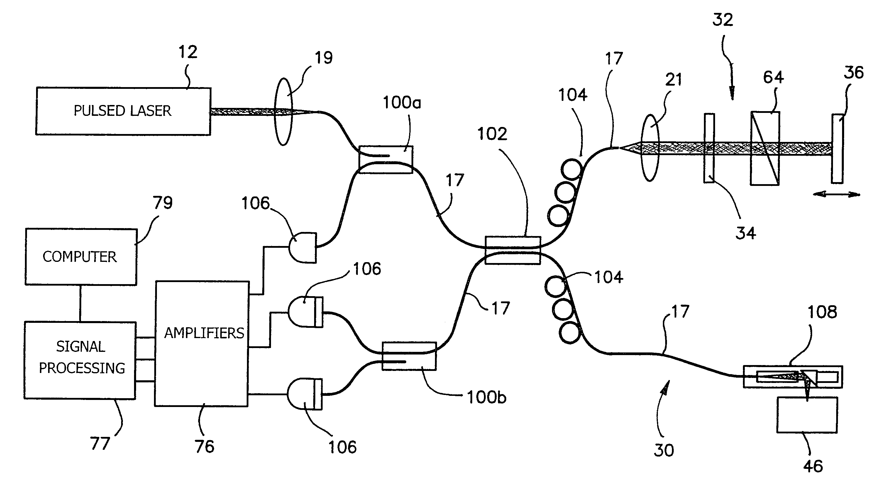
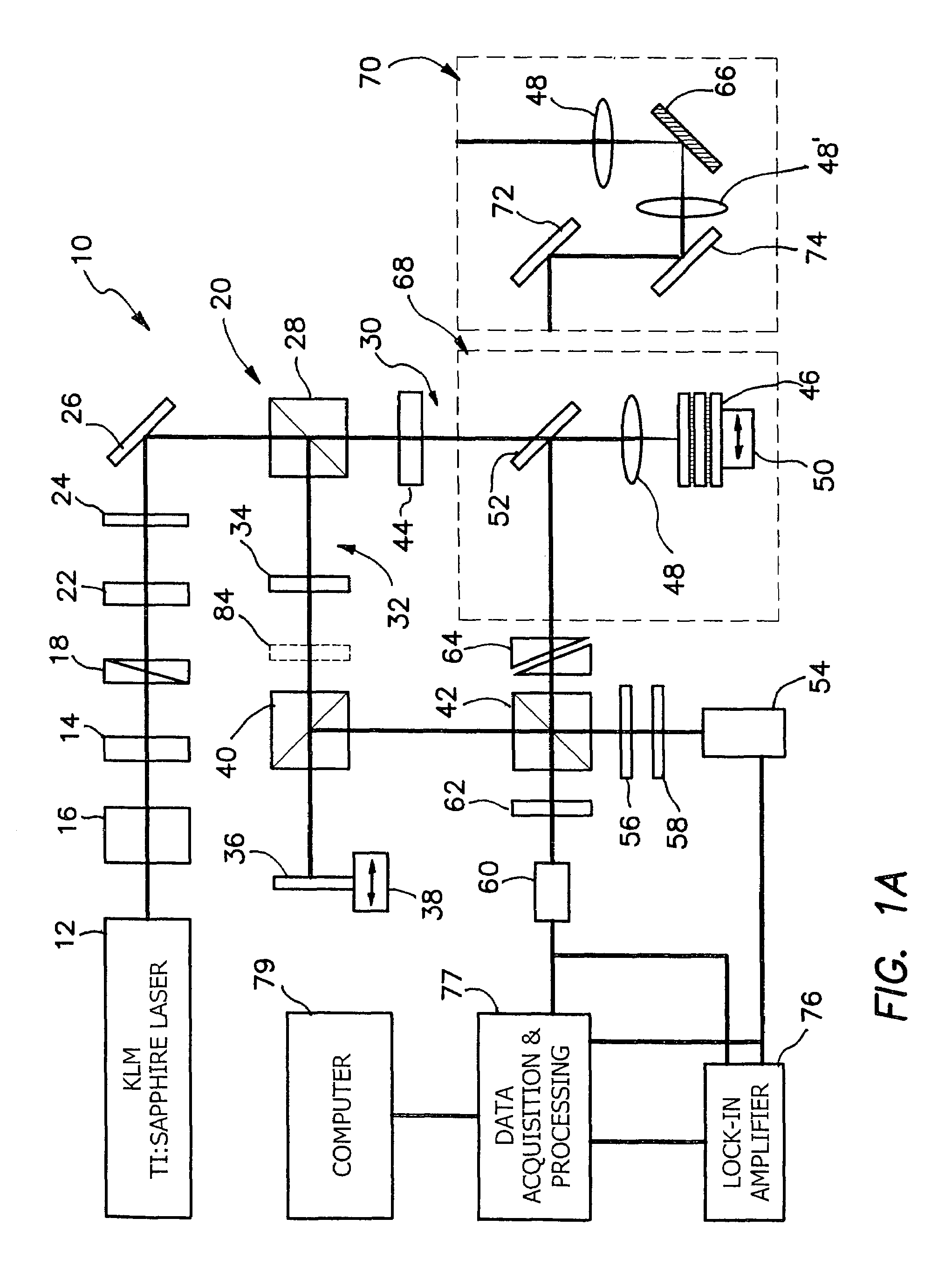
[0037]An optical tomography technique of second harmonic optical coherence tomography is described. Femtosecond laser pulses at 800 nm wavelength are used to excite second harmonics at 400 nm from a rat tail tendon and a reference nonlinear thin crystal 34. Second harmonic interference fringe signals were detected and used for image construction. A tomographic image shows the sample structure of two thin collagen layers sandwiched among glass slides as shown and described below in connection with FIG. 4c. Because of the strong dependence of second harmonic generation on molecular and tissue structures, this technique offers molecular contrast as well as resolution enhancement to the conventional optical coherence tomography.

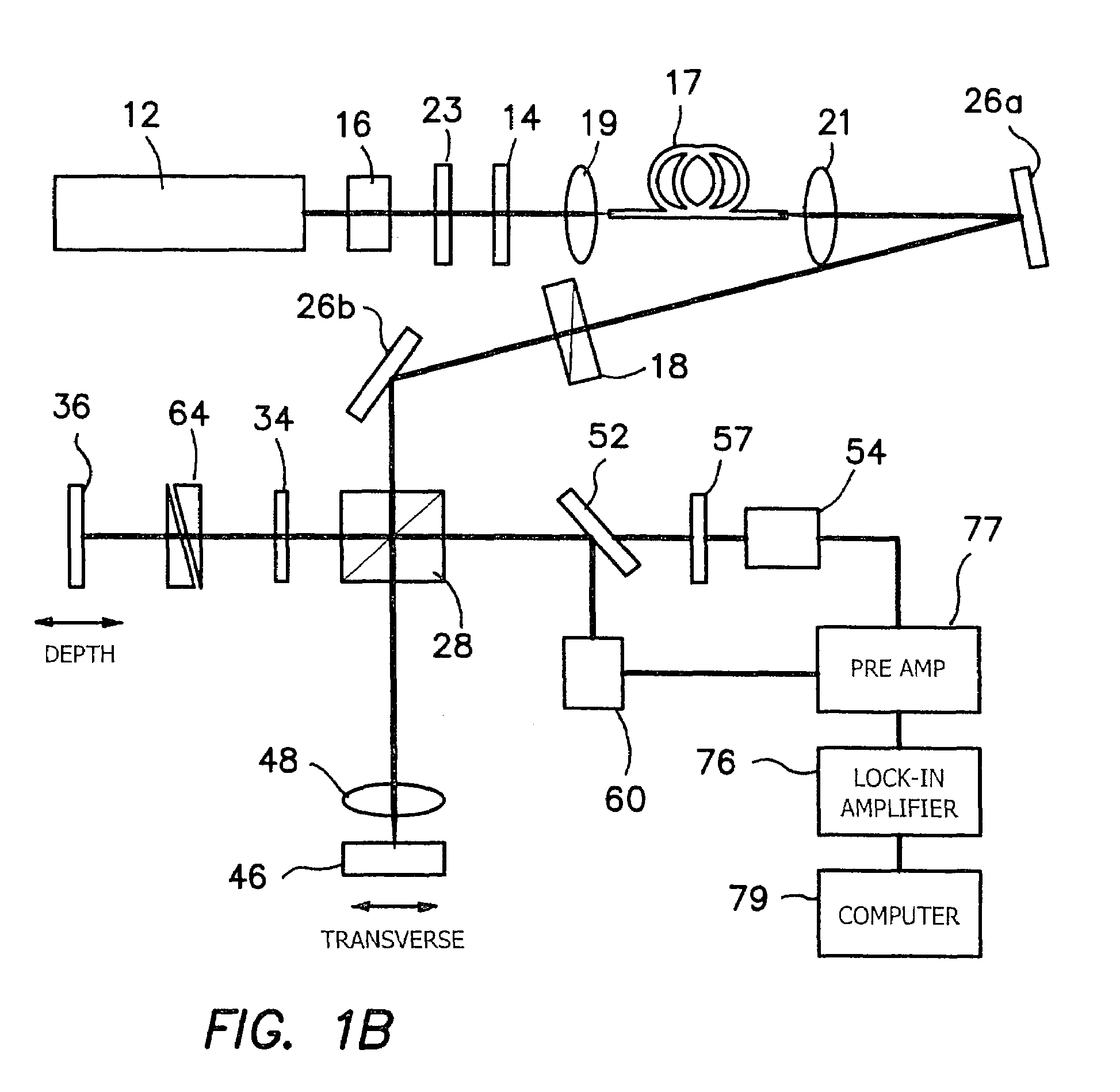
[0038]The invention discloses a high-resolution SH-OCT system 10 as diagrammatically described below in FIG. 1b. Using broadband, pulsed laser illumination and nonlinear interferometry, the system 10 combines the molecular structure sensitivity of SHG with cohere...


PUM

PropertyMeasurementUnit
thicknessaaaaaaaaaa
thicknessaaaaaaaaaa
depthsaaaaaaaaaa

Abstract

The invention is an apparatus and method for second harmonic optical coherence tomography of a sample comprising a laser coupled to an interferometer which has a reference arm and in a sample arm. A nonlinear crystal in the reference arm generates a second harmonic reference signal. The sample typically backscatters some second harmonic light into the sample arm. A broadband beam splitter optically coupled to the reference arm and sample arm combines the signals from the reference arm and sample arm into interference fringes and a dichroic beam splitter splits the interference fringes into a fundamental and second harmonic interference signal. A detector is optically coupled to the dichroic beam splitter detects interference fringes from which both an OCT and second harmonic OCT image can be constructed using a conventional data processor.

Description

RELATED APPLICATIONS [0001]The present application is related to U.S. Provisional Patent Application, Ser. No. 60 / 512,675, filed on Oct. 20, 2003, which is incorporated herein by reference and to which priority is claimed pursuant to 35 USC 119.BACKGROUND OF THE INVENTION [0002]1. Field of the Invention[0003]The invention relates to the field of optical coherence tomography using optical second harmonic generation and nonlinear optical interferometry.[0004]2. Description of the Prior Art[0005]Optical coherence tomography (OCT) is an emerging imaging technology that provides in-vivo high-resolution, cross-sectional images of biological tissues. Using coherence gating technique, OCT is capable of detecting the backscattered light from highly scattering tissues at depths of 2-3 mm. OCT imaging contrast originates from the inhomogeneities of sample scattering properties that are linearly dependent on sample refractive indices. In many instances such as pathological processes in tissue, ...

Claims


Application Information

Patent Timeline
Patent Type & Authority Patents(United States)
IPC IPC(8): G01B9/02A61B5/00G01N21/47G01N21/65
CPCA61B5/0066A61B5/0073G01N21/4795A61B5/4523G01N21/65
Inventor CHEN, ZHONGPINGJANG, YI
Owner RGT UNIV OF CALIFORNIA
Why Eureka
Try Eureka