Laser apparatus

a laser and lens technology, applied in the field of laser apparatus, can solve the problems of disturbance of the laser gas supply system, the temperature difference between the central portion and the peripheral portion of the condensing lens, and the immediate temperature difference, and achieve the effect of simple and accurate calculation and stable outpu

Inactive Publication Date: 2007-08-14
FANUC LTD
View PDF12 Cites 78 Cited by
  • Summary
  • Abstract
  • Description
  • Claims
  • Application Information

AI Technical Summary

Benefits of technology

[0018]Specifically, in the first aspect of the invention, the temperature change or the temperature of a specified component element such as discharge electrodes can be estimated and calculated based on the laser output value and the elapsed time in the design and development stage. Therefore, by adjusting the conditions for controlling or machining operation of the laser oscillator and the laser machine of the laser apparatus based on the estimated value of the temperature change or the temperature of a specified component element, a stable laser machining operation can be conducted for a long time without actually measuring the temperature of the specified component element or without using the temperature sensor. The laser output value is desirably the average value for a predetermined period of time.
[0052]Further, in the 12th aspect of the invention, the controllability can be improved as compared with the simple feedback control.

Problems solved by technology

At various points of the laser apparatus, therefore, a considerable difference arises between the temperature immediately following the start operation of the oscillator and the temperature during the steady operation thereof.
The central portion of the condensing lens in the neighborhood of the machining head is heated, for example, by the high-output laser transmitted therethrough, resulting in a temperature difference between the central portion and the peripheral portion of the condensing lens.
As a result, the laser gas expands, and therefore the laser gas supply system is disturbed.
Thus, the laser gas pressure control is upset thereby causing the irregularities of the laser output and discharge voltage.
Installation of the temperature sensors on the component elements of the laser apparatus such as the discharge electrodes and the condensing lens, however, requires a physical space.
Also, even in the case where the installation is possible, the temperature of a specified component element such as the discharge electrodes impressed with a high voltage and the central portion of the condensing lens cannot be easily measured, and therefore it is not an easy matter to continuously detect the temperature accurately while the laser apparatus is driven.
Further, these sensors, of course, are costly, and a temperature sensor of high response rate that can produce a real output within one millisecond from an output command such as for the laser is very expensive.
The temperature sensor having such a high response rate cannot be realistically used for every part of the laser apparatus.
Although the temperature of the laser gas can be stabilized within several milliseconds after starting the laser output, however, the component elements of the laser apparatus such as the optical parts making up the discharge electrodes, the discharge tube and the resonator cannot be cooled within as short a time as the laser gas can.
For this reason, the laser apparatus cannot be actually controlled properly in accordance with the temperature change of each specified component element based on the method disclosed in Japanese Unexamined Patent Publication No. 10-135542.
In these patent publications, the cooling process is not sufficiently taken into consideration, and therefore the laser apparatus disclosed in these patent publications cannot be used for the continuously-changing laser control operation.
If the control is operated in accordance with the time when the laser output is off, therefore, a higher accuracy cannot be achieved.

Method used


Image

  • Laser apparatus
  • Laser apparatus
  • Laser apparatus

Examples


Embodiment Construction

[0064]Embodiments of the invention are described below with reference to the accompanying drawings.

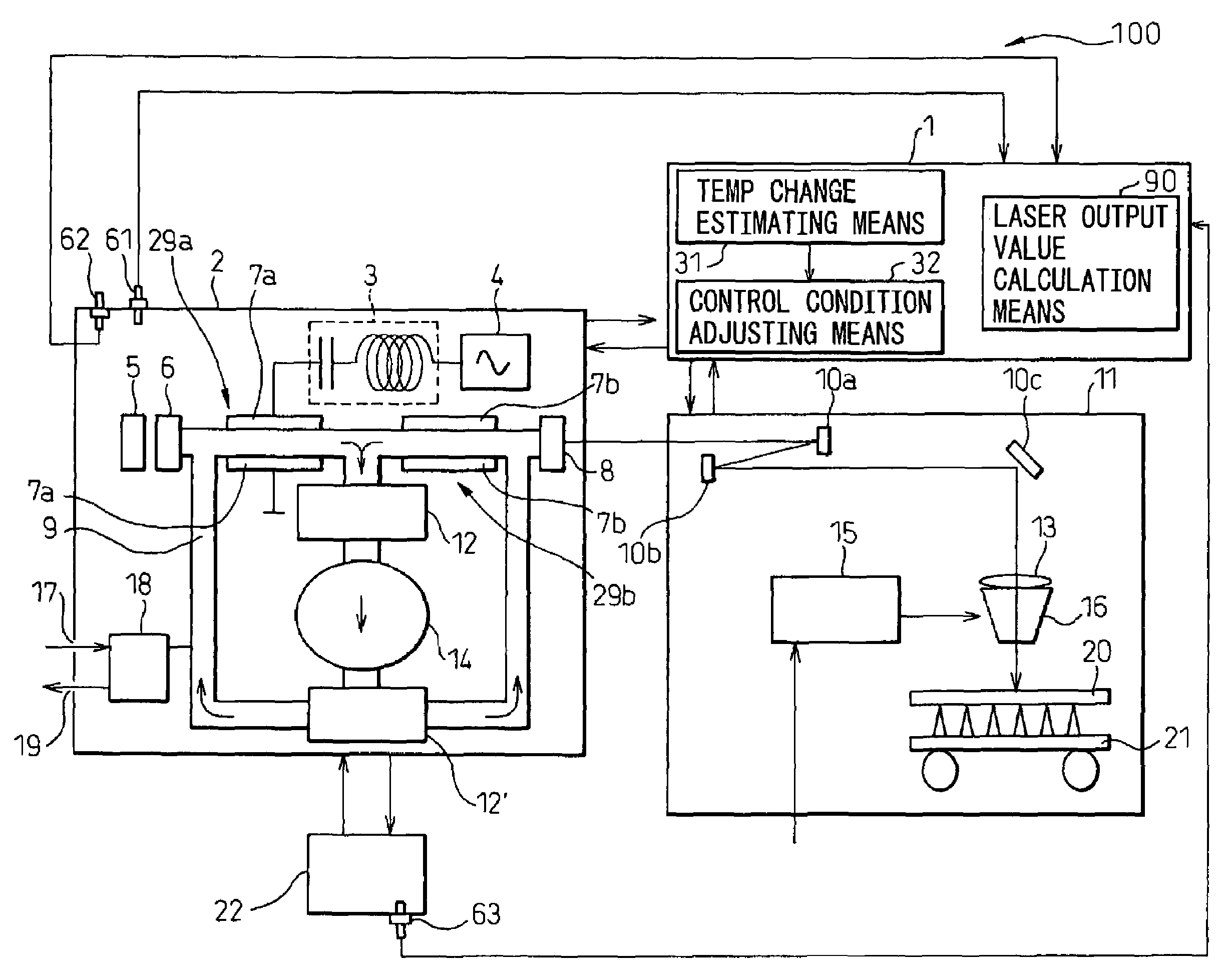
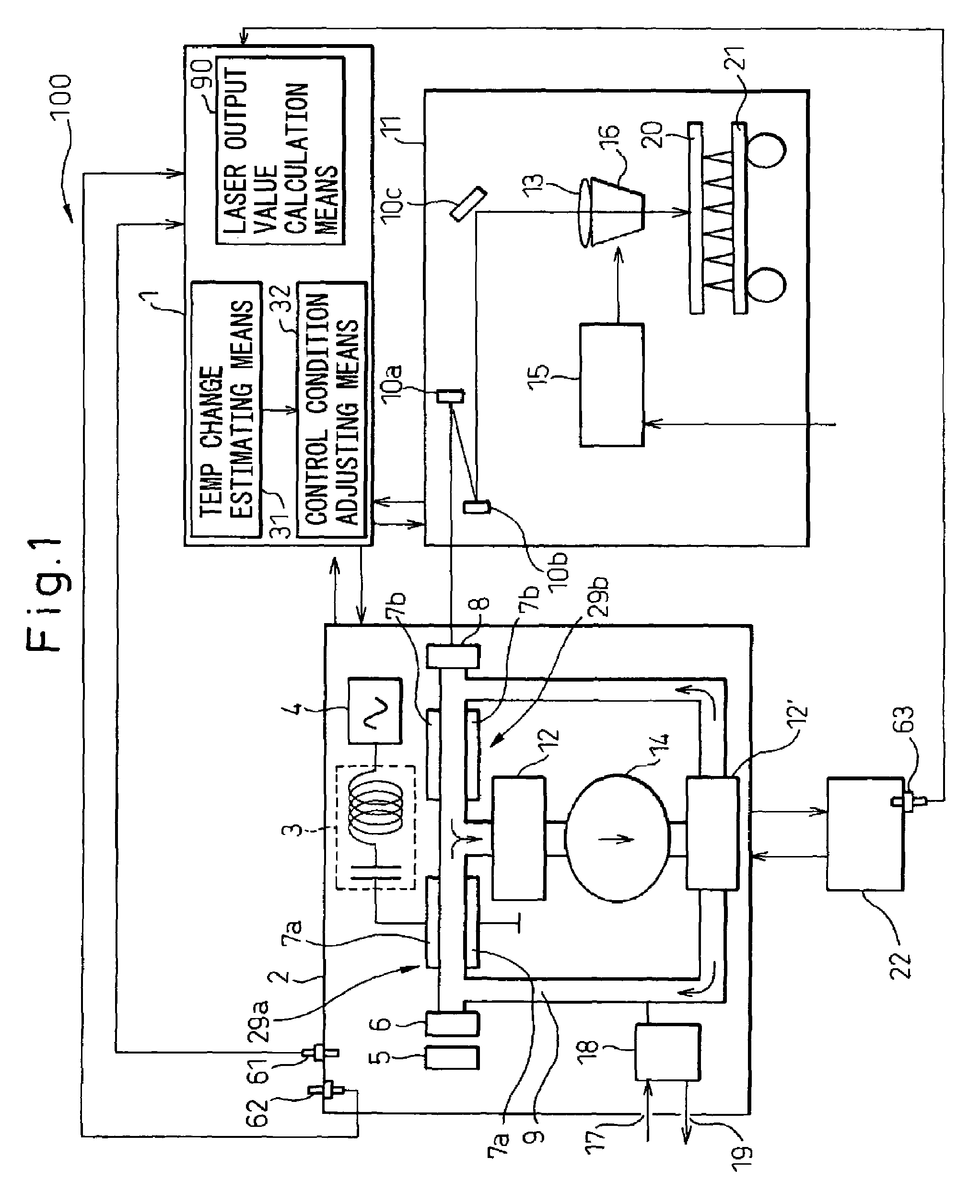
[0065]FIG. 1 is a schematic diagram showing a laser apparatus according to an embodiment of the invention. The laser apparatus 100 according to this invention includes a laser oscillator 2 and a laser machine 11, which are connected electrically to each other through a control unit 1 as shown in FIG. 1.

[0066]The laser oscillator 2 is of induction discharge excitation type and includes a discharge tube 9 connected to a laser gas pressure control system 18. The laser gas pressure control system 18 can supply the laser gas to the discharge tube 9 through a laser gas supply port 17 and discharge the laser gas from the discharge tube 9 through a laser gas discharge port 19. A rear mirror 6 (internal mirror of the resonator) having a very small partial transmissibility is arranged at an end of the discharge tube 9, and an output mirror 8 having a partial transmissibility of several tens of p...


PUM

PropertyMeasurementUnit
temperatureaaaaaaaaaa
distanceaaaaaaaaaa
pressureaaaaaaaaaa

Abstract

A laser apparatus (100) for performing the laser machining operation by condensing the laser light output from a laser oscillator (3) is disclosed. A laser output value calculation unit calculates a laser output value (L1) based on a command value (L0) issued to a laser oscillator (2). A temperature change estimating unit (31) estimates the temperature change or the temperature (Te) of specified component element(s) (7a, 7b) of the laser apparatus based on the elapsed time (t) and the laser output value calculated by the laser output value calculation unit. An adjusting unit (32) adjusts the conditions for controlling the laser or the conditions for laser machining based on the temperature change or the temperature of the specified component element estimated by the temperature change estimating unit. A stable laser machining operation is performed without a temperature sensor. The laser output value (L1) may be measured by a laser power sensor (5).

Description

BACKGROUND OF THE INVENTION[0001]1. Field of the Invention[0002]This invention relates to a laser apparatus including a laser oscillator for producing a laser output by exciting a gas or a solid medium, or a laser machine, namely laser beam machine, for a machining operation such as cutting or welding, using the laser output from the laser oscillator.[0003]2. Description of the Related Art[0004]Generally, a laser apparatus mainly comprises a laser oscillator, an optical transmission system for transmitting and condensing light, a device for driving a work, auxiliary equipment and a control unit for controlling these component parts. An ordinary laser apparatus used for the laser cutting operation, for example, includes a laser oscillator, a machining table driven in X, Y and Z directions, an optical transmission system having a reflector, a laser machining head for condensing the laser light, an assist gas supply system for supplying an assist gas to the laser head, a cooling water ...

Claims


Application Information

Patent Timeline
Patent Type & Authority Patents(United States)
IPC IPC(8): H01S3/121B23K26/00H01S3/00
CPCB23K26/422B23K26/426H01S3/134H01S3/036H01S3/041H01S3/073H01S3/0975H01S3/10069B23K26/702B23K26/705
Inventor MORI, ATSUSHIOKAZAKI, RYOMAANDO, MINORU
Owner FANUC LTD
Why Eureka
Try Eureka