Rare earth magnet and method for production thereof

a technology earth magnets, applied in the field of rare earth magnets, can solve the problems of oxidation and ignition, deterioration of sintering degree, and affect the degree of sintering badly

Inactive Publication Date: 2007-08-21
HITACHI METALS LTD
View PDF22 Cites 29 Cited by
  • Summary
  • Abstract
  • Description
  • Claims
  • Application Information

AI Technical Summary

Benefits of technology

[0024]The rare earth permanent magnet of the present invention is a rare earth permanent magnet containing an R2T14Q phase (R is a rare earth element, T is a transition metal element, and Q is at least one element selected from the group consisting of B, C, N, Al, Si, and P) as a main phase, wherein the rare earth element contains at least one kind of element RL selected from the group consisting of Nd and Pr, and at least one kind of element RH selected from the group consisting of Dy, Tb, and Ho, the element RH accounts for 10 at % or more of the total of the contained rare earth element, and a mole fraction of the element RH included in the R2T14Q phase is larger than a mole fraction of the element RH in the total of the contained rare earth element.

Problems solved by technology

The element R existing in the grain boundary phase involves a problem that the element RH does not contribute to the increase in the coercive force.
There is another problem that the existence of a lot of element RH in the grain boundary deteriorates the degree of sintering.
The problem is serious when the ratio of the element RH in the material alloy is 1.5 at % or more, and the problem is remarkable in the case where the ratio is 2.0 at % or more.
Such super fine powder may easily cause problems of oxidation and ignition, and badly affect the sintering, so that the super fine powder is removed during the pulverization process.
As described above, there is a problem that, in the element RH in the quenched alloy, a portion existing in the grain boundary phase is not effectively used for the purpose of improving the coercive force.
The element RH is a rare element, and is expensive.
According to the technique, however, a Dy oxide which does not contribute to the coercive force remains in the grain boundary phase, so that the use amount of Dy cannot be sufficiently reduced.
The technique, however, involves a problem that the existence ratio of the main phase is lowered due to the existence of Sn which does not contribute to the magnetic properties, thereby lowering the saturation magnetization.
However, the addition of any of the elements results in the generation of a phase which does not contribute to the magnetic properties, so that there exist problems such as that the saturation magnetization is lowered, or that the magnetization of the main phase is lowered.
However, if the thermal treatment at such temperatures is performed, the fine structure which is an advantage of the strip casting method is lost, so that the coercive force is lowered in the case where the grain distribution of powder is the same.
Accordingly, if the hydrogen decrepitation process is performed before the rapidly solidified alloy produced by the strip casting method or the like is finely pulverized, a lot of element RH existing in the grain boundary phase is wastefully lost.
Thus, there is a problem that the use efficiency of the element RH is further lowered.

Method used


Image

  • Rare earth magnet and method for production thereof
  • Rare earth magnet and method for production thereof
  • Rare earth magnet and method for production thereof

Examples


embodiments

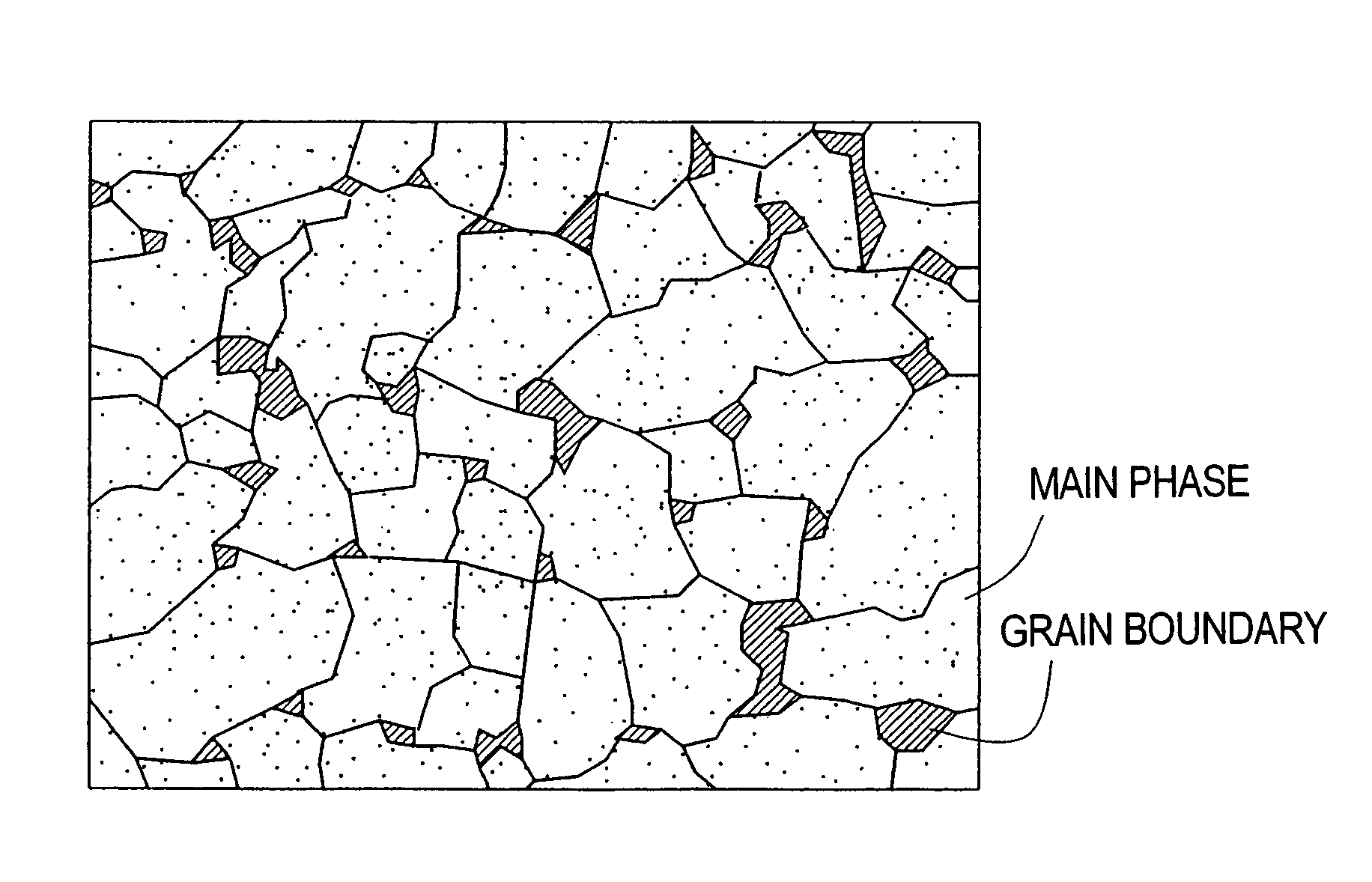
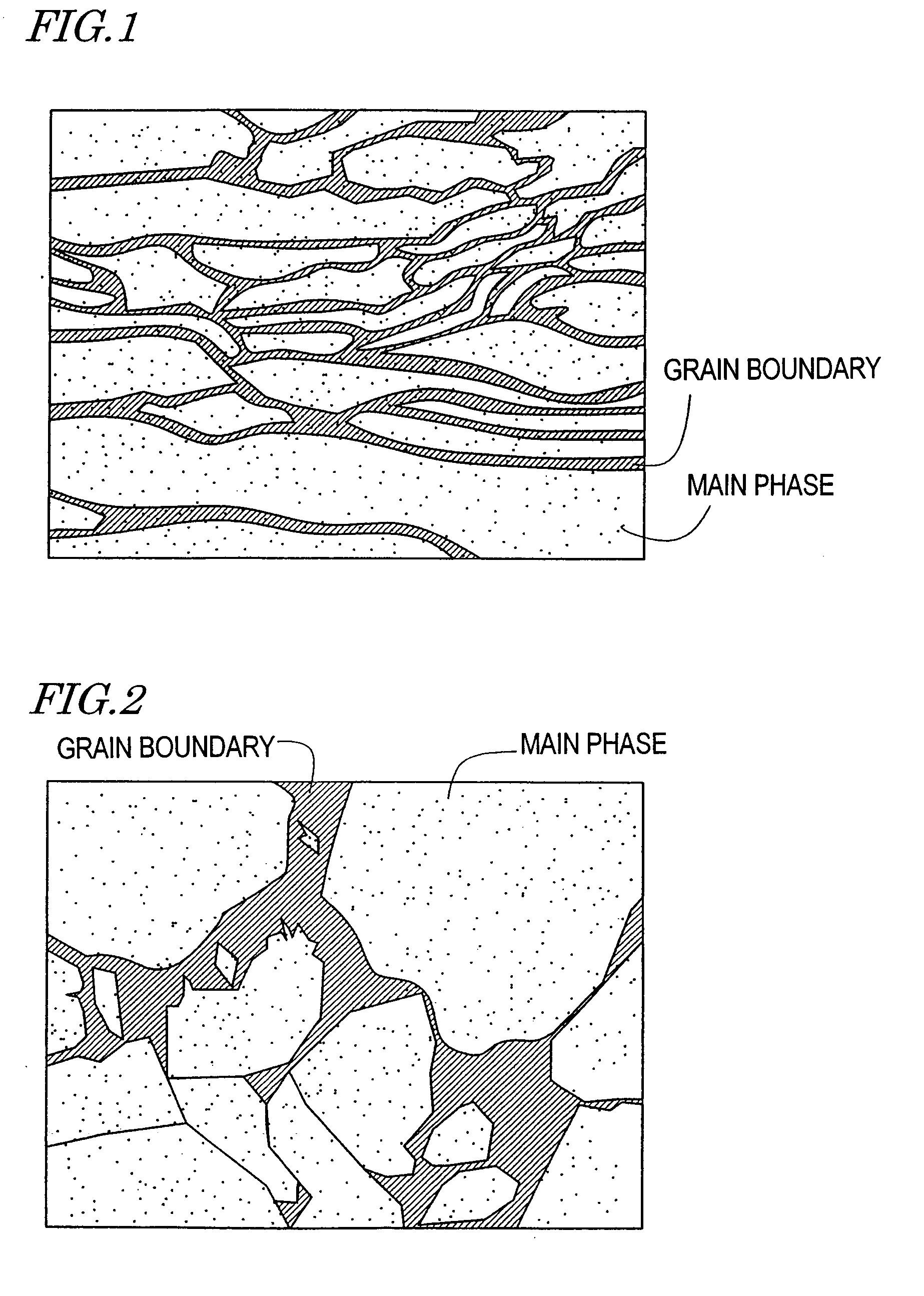
[0064]First, a molten alloy having a composition of 22% Nd-10% Dy-0.25% Al-0.05% Cu-1.0% B-the residual portion Fe in mass ratios was rapidly solidified by a strip casting method, so as to produce a quenched and solidified alloy with the above-mentioned composition (alloy A). As a relative example, an alloy (alloy B) was produced by an ingot method. FIG. 1 and FIG. 2 are schematic diagrams showing structures of the alloy A and the alloy B, respectively. In the attached figures, Dy is schematically shown as dots. As shown in FIG. 1, in the alloy A, Dy uniformly exists in the main phase and the grain boundary phase. As is seen from the comparison between FIG. 1 and FIG. 2, the amount of Dy existing in the grain boundary phase is larger in the alloy A than in the alloy B.

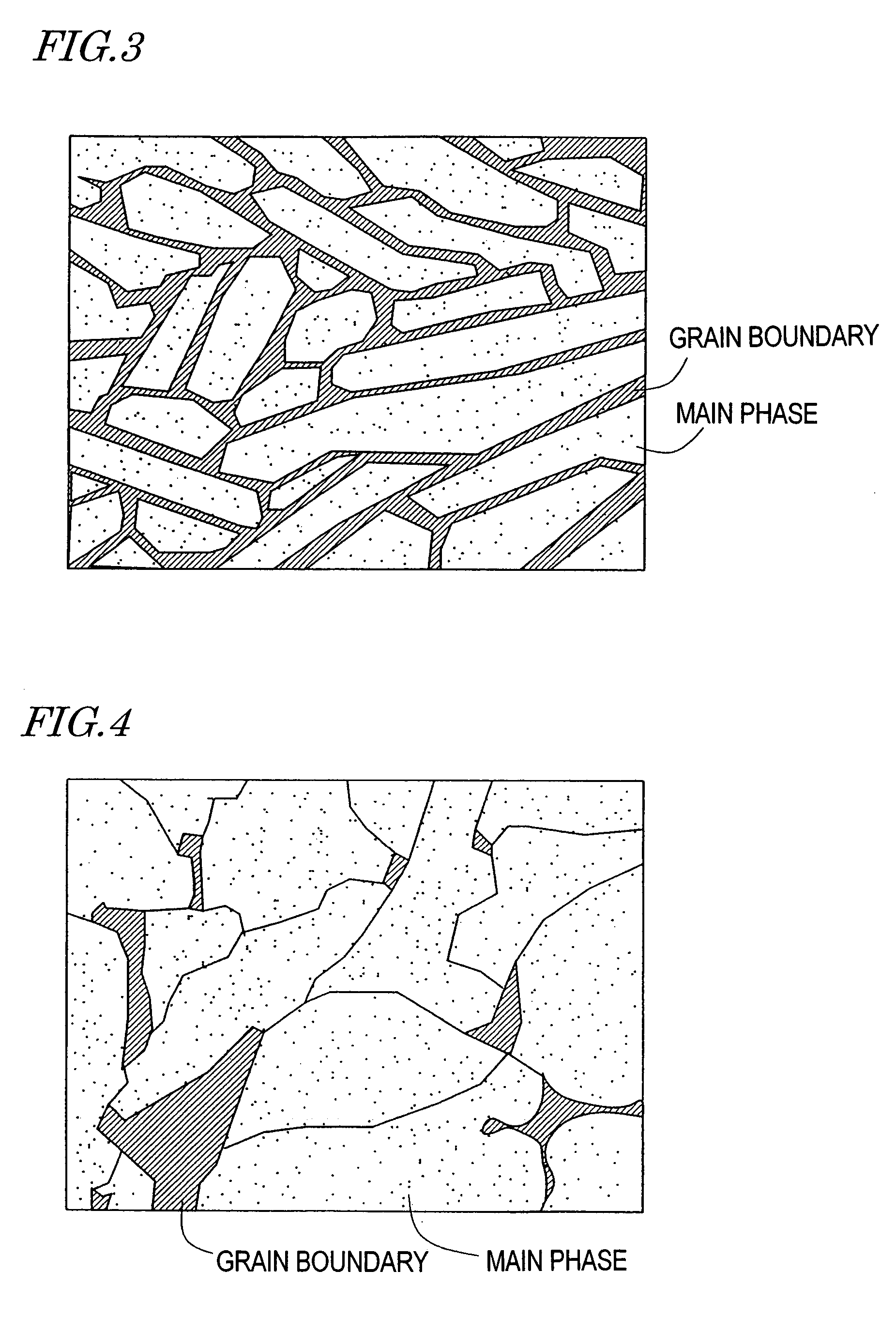
[0065]Next, for the alloys A and B, thermal treatment at 600° C. for 1 hour was performed in an Ar atmosphere. Structures of the alloys before and after the thermal treatment are shown in FIG. 3 and FIG. 4, respectivel...


PUM

PropertyMeasurementUnit
temperatureaaaaaaaaaa
thicknessaaaaaaaaaa

Abstract

In a rare earth magnet, an added heavy rare earth element RH such as Dy is effectively used without any waste, so as to effectively improve the coercive force. First, a molten alloy of a material alloy for an R-T-Q rare earth magnet (R is a rare earth element, T is a transition metal element, and Q is at least one element selected from the group consisting of B, C, N, Al, Si, and P), the rare earth element R containing at least one kind of element RL selected from the group consisting of Nd and Pr and at least one kind of element RH selected from the group consisting of Dy Tb, and Ho is prepared. The molten alloy is quenched, so as to produce a solidified alloy. Thereafter, a thermal treatment in which the rapidly solidified alloy is held in a temperature range of 400° C. or higher and lower than 800° C. for a period of not shorter than 5 minutes nor longer than 12 hours is performed. By the thermal treatment, the element RH can be moved from the grain boundary phase to the main phase, so that the coercive force is increased.

Description

TECHNICAL FIELD[0001]The present invention relates to a rare earth magnet, and a production method thereof.BACKGROUND ART[0002]Presently, two kinds of rare earth magnets: samarium / cobalt-based magnet, and a neodymium / iron / boron-based magnet are widely used in various fields. The neodymium, iron / boron-based magnet exhibits the highest magnetic energy product of various kinds of magnets, and the price thereof is relatively low, so that the neodymium / iron / boron-based magnet is positively adopted in various electronic equipments.[0003]The neodymium / iron / boron-based magnet is a magnet having Nd2Fe14B crystals as a main phase, and, in some cases, the magnet is more generally referred to as “an R-T-B magnet” Herein, R is a rare earth element and / or Y (yttrium), T is mainly Fe and a transition metal represented by Ni and Co, and B is boron. An element such as C, N, Al, Si, and / or P can be substituted for part of B, so that, in this specification, at least one element selected from the group...

Claims


Application Information

Patent Timeline
Patent Type & Authority Patents(United States)
IPC IPC(8): H01F1/057C22C38/00C22C38/06C22C38/10H01F1/058H01F1/059
CPCC22C28/00C22C38/002C22C38/005C22C38/06C22C38/10C22C45/02H01F1/0571H01F1/0573H01F1/0577H01F1/058H01F1/059
Inventor TOMIZAWA, HIROYUKIKANEKO, YUJI
Owner HITACHI METALS LTD
Why Eureka
Try Eureka