
Catalyst carrier holding material and catalytic converter

a technology of catalytic converter and carrier, which is applied in the direction of combination devices, machines/engines, chemical/physical processes, etc., can solve the problems of material not being able to withstand extended use, deterioration of fibers, and inability to apply insulation materials such as those disclosed in the aforementioned unexamined patent publications for operating temperatures in such high ranges

Active Publication Date: 2007-08-28
3M INNOVATIVE PROPERTIES CO
View PDF16 Cites 48 Cited by
  • Summary
  • Abstract
  • Description
  • Claims
  • Application Information

AI Technical Summary

Benefits of technology

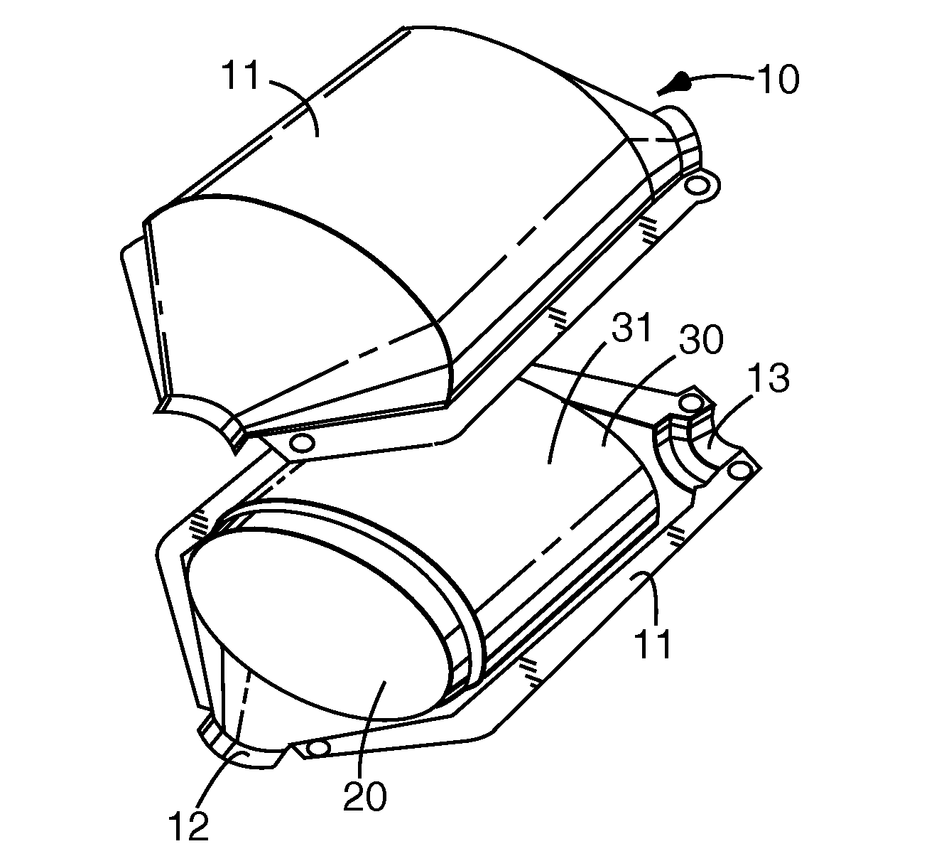
The present invention provides a new catalyst carrier holding material for use in catalytic converters. This material is made of inorganic fibers containing alumina and silica, with a mullite ratio of greater than 30% and less than 75%. This material has excellent heat resistance, high compression resistance, and wind erosion resistance, making it ideal for use in catalytic converters. The material can be used to hold a catalyst carrier and is particularly useful in automobiles and other vehicles with internal combustion engines. The invention also provides a catalytic converter with the new material and a casing, as well as a method for making the material.

Problems solved by technology

However, insulating materials such as those disclosed in the aforementioned unexamined patent publications cannot be applied for operating temperatures in such high ranges, because of their composition and others.
If the alumina to silica weight ratio is outside of this range, deterioration of the fibers occurs more rapidly due to crystallization and crystal growth at high temperature, such that the material cannot withstand use for extended periods.
Nevertheless, with the exhaust gas purification apparatus holding material described in Japanese Unexamined Patent Publication (Kokai) No. 7-286514, not only are the desired function and effect exhibited only when using alumina fibers having a mullite composition in the aforementioned limited range, but using alumina fibers with a low mullite ratio (for example, a few percent) results in increased plastic deformation and poor bearing retention (compression resistance) in high temperature ranges.
Furthermore, since the compression resistance tends to rapidly decrease as a result of use at high temperature even if the compression resistance at the initial stage is satisfactory, it is very difficult to maintain high compression resistance for extended periods.
On the other hand, when using alumina fibers with a high mullite ratio (for example, 75% or more), the compression resistance in high temperature ranges is improved because of reduced plastic deformation, but the higher brittleness which also occurs results in easier breakage of the alumina fibers, such that it is impossible to avoid worsening of “wind erosion” (a phenomenon in which the holding material crumbles at both ends due to wind pressure).
As this wind erosion continues to progress, it causes dwindling of the surface area of the holding material which is supposed to exhibit holding force, and this leads to lower overall compression resistance and thus inconveniences such as shifting of the catalyst carrier.

Method used


Image

  • Catalyst carrier holding material and catalytic converter
  • Catalyst carrier holding material and catalytic converter

Examples


example 1

Manufacture of Catalyst Carrier Holding Materials (Mats)

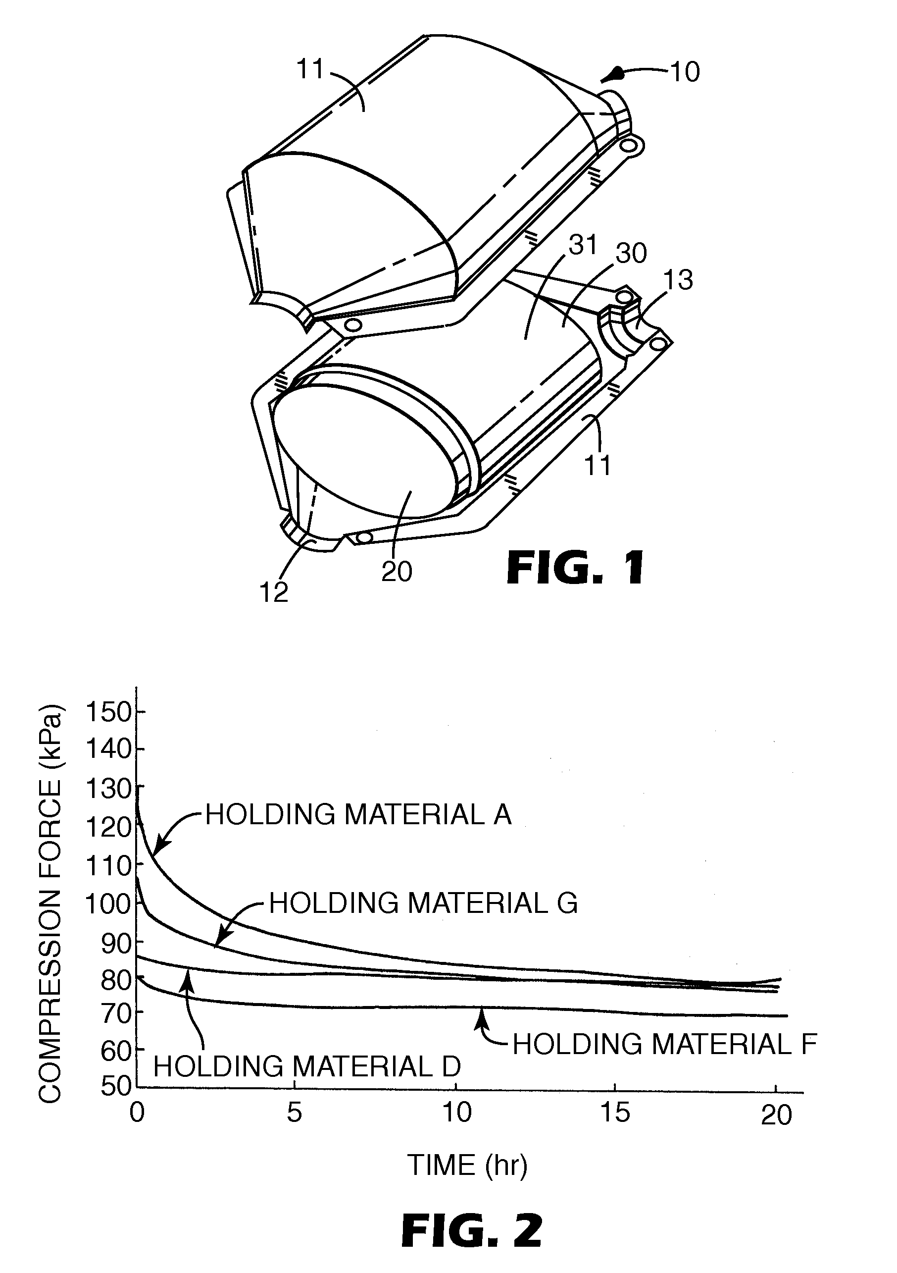
[0051]The following seven different mat-shaped catalyst carrier holding materials were manufactured using inorganic fibers composed of or comprising the two components alumina and silica, having an alumina / silica mixing ratio of 72:28 and different mullite ratios (2%, 35%, 60%, 70% and 78%).

[0052]For manufacture of each of the holding materials, first the inorganic fibers (a mixture of two different inorganic fibers for manufacture of holding material G) and the organic binder (trade name: “LX-816”) (flocculating agent) were placed in water, and the fibers were opened and mixed. Next, the mixture was gently stirred to prepare a slurry. The slurry was then sheeted and molded into the desired mat shape. The molded product was squeezed to remove the excess moisture, and then the mat was pressed while heating to dryness at the prescribed temperature. This yielded the following catalyst carrier holding materials each having a thickn...

example 2

[0070]The desirable properties experienced with the present invention can be obtained from a mat made by blending low mullite content fiber (e.g., less than 10%) and high mullite content fiber (e.g., greater than 70%). Such properties can also be obtained, for example, with a layered mat, using low mullite content fibers for at least one layer and high mullite content fibers for at least one other layer.

[0071]Sample mat-shaped catalyst carrier holding materials were made as described for Example 1 above with 2% and 78% mullite content fibers. Fiber blend ratios and layering ratios were figured as average mullite % calculated by fiber weight and its fiber % mullite. For example, the average mullite % of a mat made of a 50 / 50 blend of these mullite fibers (i.e., 2% and 78% mullite content fibers) is 40%. Compression at 900 deg.C. and erosion resistance were evaluated and results were summarized below in Table 2.

Inclination is b in approximated equation: Y=aXb

[0072]

TABLE 2InclinationEx...


PUM

PropertyMeasurementUnit
operating temperaturesaaaaaaaaaa
lengthaaaaaaaaaa
lengthaaaaaaaaaa

Abstract

To provide a catalyst carrier holding material which is particularly useful for catalytic converters, by exhibiting heat resistance and high compression resistance in high temperature ranges, as well as excellent wind erosion resistance. The catalyst carrier holding material comprises inorganic fibers comprising alumina and silica, and the mullite ratio of the inorganic fibers is in the range of greater than 30% and less than 75%, and preferably in the range of 35% to 70%.

Description

CROSS REFERENCE TO RELATED APPLICATIONS[0001]This application is a national stage filing under 35 U.S.C. 371 of International Application No. PCT / US02 / 19904 filed Jun. 21, 2002, which claims priority to the Japanese Patent Application No. 2001-190005 filed Jun. 22, 2001, the disclosure of which is incorporated by reference in its / their entirety herein.FIELD OF THE INVENTION[0002]The present invention relates to a catalyst carrier holding material, and more specifically, it relates to a catalyst carrier holding material with excellent heat resistance, compression resistance and wind erosion resistance. The present invention also relates to a catalytic converter packed with the catalyst carrier holding material. The catalytic converter of the invention can be advantageously utilized for treatment of exhaust gas from an internal combustion engine, such as that of an automobile. The catalytic converter is preferably a catalytic converter holding a catalytic element within its casing.BAC...

Claims


Application Information

Patent Timeline
Patent Type & Authority Patents(United States)
IPC IPC(8): F01N3/08B01J21/16B01J35/04B01J35/06B32B18/00C04B30/02F01N3/28F01N13/18
CPCB01J21/16B01J35/06B32B18/00C04B30/02C04B35/62625F01N3/2853F01N3/2864F01N13/1888B01J35/04C04B14/4656C04B2237/704C04B2111/00413C04B2111/0081C04B2235/5228F01N2330/06F01N2530/04F01N2530/06C04B2237/584C04B2237/582C04B2237/341C04B2237/343C04B2237/38B01J35/56B01J35/58
Inventor WATANABE, TOSHIYUKI
Owner 3M INNOVATIVE PROPERTIES CO
Learn More