Low thermal drift, tunable frequency voltage controlled oscillator

a technology of tunable frequency voltage and controlled oscillator, which is applied in the direction of oscillation generator, pulse technique, modulation, etc., can solve the problems of limiting or affecting the performance of the pll itself, and affecting the performance of the device in which the pll is employed

Active Publication Date: 2007-08-28
SYNERGY MICROWAVE CORP
View PDF60 Cites 9 Cited by
  • Summary
  • Abstract
  • Description
  • Claims
  • Application Information

AI Technical Summary

Benefits of technology

[0025]In yet another aspect of the present invention, an apparatus is provided. The apparatus preferably comprises a phase lock loop for generating a clock signal used to transmit or recover information communicated from or to the apparatus, the phase lock loop comprising a voltage a-controlled oscillator for generating the clock signal, the voltage controlled oscillator comprising: a cascode configured device having first, second and third terminals; a plurality of resonators; and first circuitry coupled between the plurality of resonators and the second terminal of the cascode configured device, the circuitry being operable as a evanescent mode buffer to compensate for changes in the capacitance of the oscillator during operation.

Problems solved by technology

The dynamic operating range and noise performance of a VCO may limit or affect the performance of the PLL itself, which in turn may affect the performance of the device in which the PLL is employed, e.g., RF transceivers, a cell phone, a modem card, etc.
Despite the continuous improvement in VCO technology, low phase noise typically remains a bottleneck and poses a challenge to RF transceiver (transmitter—receivers) design.
In addition, oscillator / VCO design typically poses a challenge to the RF trans-receiver system.
This is typically considered due to the more demanding parameters of the VCO design: low phase noise, low power consumption and wide frequency tuning range.
For example, in a receiver, the phase noise of the local oscillator limits the ability to detect a weak signal in the presence of a strong signal in an adjacent channel.
In a transmitter, phase noise results in energy being transmitted outside the desired channel or band.
Improvements in oscillator / VCO technology have continued with time, yielding ever-smaller sources with enhanced phase noise and tuning linearity but the phenomena of the thermal drift over the temperature range (−40° C. to +85° C.) has not been properly addressed.
On the other hand, SAW resonators are typically used in oscillators as a two-port resonator and have a relatively small pull-in range that usually does not support a wide enough tuning range to compensate for tolerances due to the circuit components.
This typically limits the amount of correction that can be made to compensate for the tolerances of the circuit components and thermal drift over the operating temperature range (−40° C. to +85° C.).
In addition, SAW devices are comparatively expensive compared to CROs (ceramic resonator based oscillator) and their availability and performance are limited to a select frequency and a relatively narrow operating temperature range (−20° C. to +70° C.).
This generally makes them unsuitable for operating in stringent temperature environments and / or low cost applications.

Method used


Image

  • Low thermal drift, tunable frequency voltage controlled oscillator
  • Low thermal drift, tunable frequency voltage controlled oscillator
  • Low thermal drift, tunable frequency voltage controlled oscillator

Examples


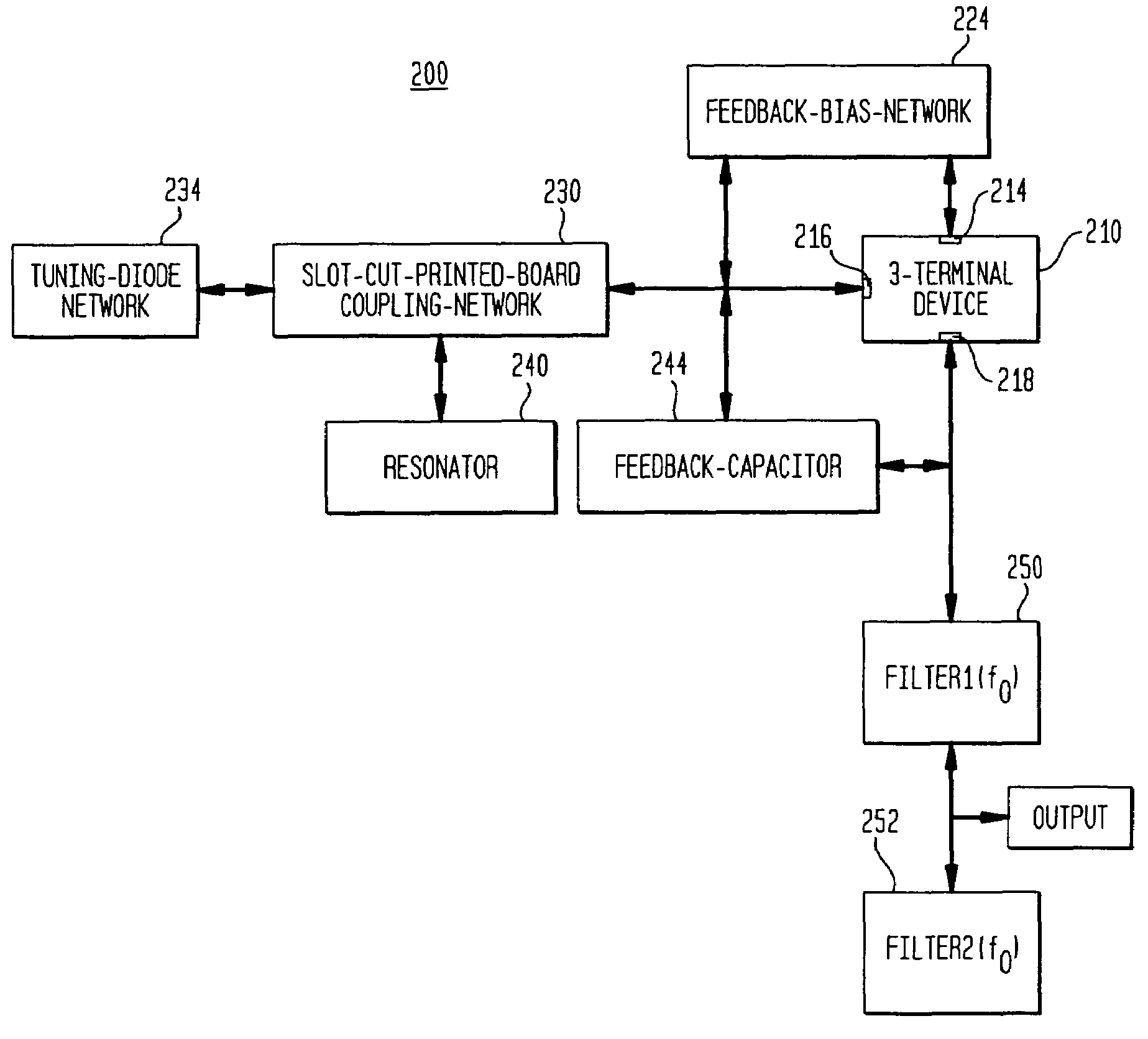
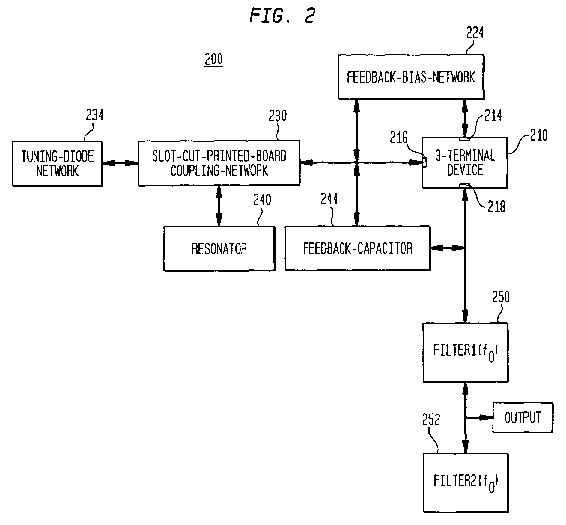
Embodiment Construction

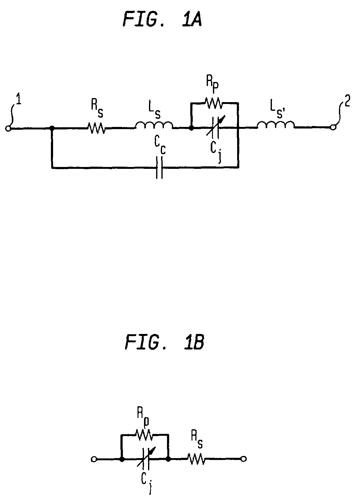
[0043]FIGS. 1A and 1B depict circuits that illustrate a tuning diode using resistors, capacitors and inductors. As shown in FIG. 1A, a tuning diode may be depicted as a two-port device (as shown, ports 1 and 2) having a resistor Rs connected to port 1 and in series with an inductor Ls. Rs and Ls are connected in series to resistor Rp and a variable capacitor Cj, which are in parallel with each other. Cj reflects the junction capacitance of the tuning diode and is variable in response to temperature changes. The circuit further includes a capacitor Cc in parallel with Rs, Ls and Cj between ports 1 and 2 and an inductor Ls, between port 2, Cj, Cc and Rp, as shown.

[0044]FIG. 1B shows a simplified equivalent circuit of a tuning diode and includes resistor Rp in parallel with capacitor Cc. The capacitor Cc is also in series with resistor Rs.

[0045]With reference to FIGS. 1A and 1B, the expression for the junction capacitance of the tuning diode under a reverse bias condition is given by:

[...


PUM


Abstract

An oscillator comprising a cascode configured device having first, second and third terminals, a plurality of resonators and first circuitry coupled between the plurality of resonators and the second terminal of the cascode configured device. The first circuitry is preferably operable as an evanescent mode buffer to compensate for changes in the capacitance of the oscillator during operation.

Description

CROSS-REFERENCE TO RELATED APPLICATIONS[0001]This application is a continuation-in-part of U.S. patent application Ser. No. 11 / 007,861, filed Dec. 9, 2004, which claims the benefit of the filing date of U.S. Provisional Patent Application Nos. 60 / 527,957, filed Dec. 9, 2003; 60 / 528,670, filed Dec. 11, 2003; and 60 / 563,481, filed Apr. 19, 2004, the disclosures of which are hereby incorporated herein by reference. This application also claims the benefit of the filing date of U.S. Provisional Patent Application Nos. 60 / 589,090, filed Jul. 19, 2004, and 60 / 601,823 filed Aug. 16, 2004, the disclosures of which are hereby incorporated herein by reference.BACKGROUND OF THE INVENTION[0002]A voltage controlled oscillator (VCO) or oscillator is a component that can be used to translate DC voltage into a radio frequency (RF) voltage or signal. The magnitude of the output signal is dependent on the design of the VCO circuit and the frequency of operation is determined, in part, by a resonator ...

Claims


Application Information

Patent Timeline
Patent Type & Authority Patents(United States)
IPC IPC(8): H03B5/12H03B5/18H03B1/00H03B5/04H03B5/32H03K7/00H03L7/099
CPCH03B5/04H03B5/1847H03B5/32H03L7/099H03B2200/002H03B2201/0208
Inventor ROHDE, ULRICH L.PODDAR, AJAY KUMARPATEL, PARIMALBADEA, DANIELSCHOEPF, KLAUS JUERGEN
Owner SYNERGY MICROWAVE CORP
Why Eureka
Try Eureka