Rear projection imaging system with image warping distortion correction system and associated method

a rear projection imaging and distortion correction technology, applied in the field of micro-display-based rear projection imaging systems, can solve the problems of complex optical distortion, the depth of the cabinet or enclosure, and achieve the effects of reducing the depth of the cabinet or enclosure, and reducing the depth of the micro-display-based rear projection imaging system

Active Publication Date: 2007-08-28
FAKESPACE LABS
View PDF28 Cites 26 Cited by
  • Summary
  • Abstract
  • Description
  • Claims
  • Application Information

AI Technical Summary

Problems solved by technology

One drawback of microdisplay based rear projection imaging systems, at least compared to plasma and direct view LCD imaging systems, is the depth of the cabinet or enclosure.
Reducing the depth of a microdisplay based rear projection imaging system requires either the use of expensive, precision projection optics or the sacrifice of displayed picture quality.
Complex optical distortions result due to this acute projection angle and the wide-angle, short focal length lenses and optics necessary to achieve high magnification in a very short distance.
These spatial and lens requirements result in geometric distortions such as keystones, pincushion effects, and anamorphic effects.
Anamorphic effects also result from off axis projection, and cause unequal magnification of above- and below-axis parts of the image.
All these effects, unless corrected for, combine together to result in a warped, distorted image on the display screen.
The tight tolerances associated with the precision manufacturing requirements further increase manufacturing costs.
Computing the predetermined warp map is a complicated and involved process requiring computed three-dimensional ray traces.
Both the lens based solution and the pre-warping based solution to correcting geometric distortions on microdisplay rear projection imaging systems suffer potential problems once the imaging systems are manufactured.
If a rear projection imaging system is dropped or jostled during shipping, or if mounting fixture material properties relax as the imaging system ages, the optics and microdisplays may come out of alignment and cause the aforementioned geometric distortions.
Less severe alignment problems such as changes in humidity or barometric pressure can cause the enclosure cabinet or mounts to warp and cause the misalignment of the different units as well.
Chromatic aberrations, or shifts in the color of an image, can likewise result from both rough handling of the imaging system and environmental changes.
As stresses on projection optics change due to mounting fixture warping, the physical shape of the lens may change, causing issues with color resolution.
Stress birefringence resulting from mounting fixture warping impairs the way optics handle polarized light.
This is a considerable problem with imagers that require the use of polarized light such as microdisplays like LCOS and HTPS.
Chromatic shift problems may also occur over time as an illumination bulb ages.
This re-alignment can only solve minor problems and must be performed by a trained technician.
There is no easy way for a consumer to quickly calibrate or realign the projection optics in an imaging system.
There is also no current method for correcting problems stemming from optics or projection systems that are manufactured slightly out of tolerance.
All of these distortion problems may result from manufacturing errors, misalignment over time, chromatic shifts in the lamp bulb, and the like.

Method used


Image

  • Rear projection imaging system with image warping distortion correction system and associated method
  • Rear projection imaging system with image warping distortion correction system and associated method
  • Rear projection imaging system with image warping distortion correction system and associated method

Examples


Embodiment Construction

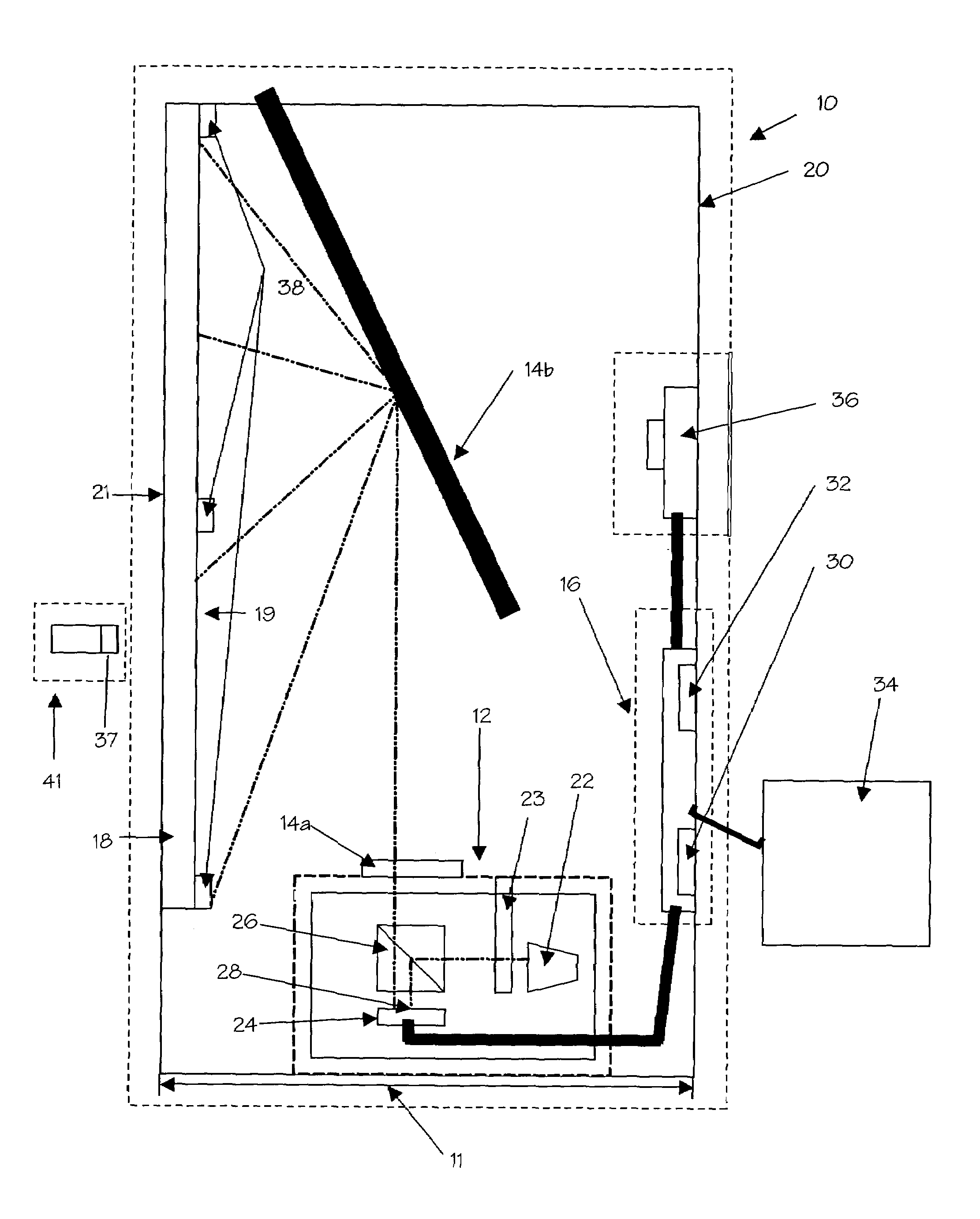
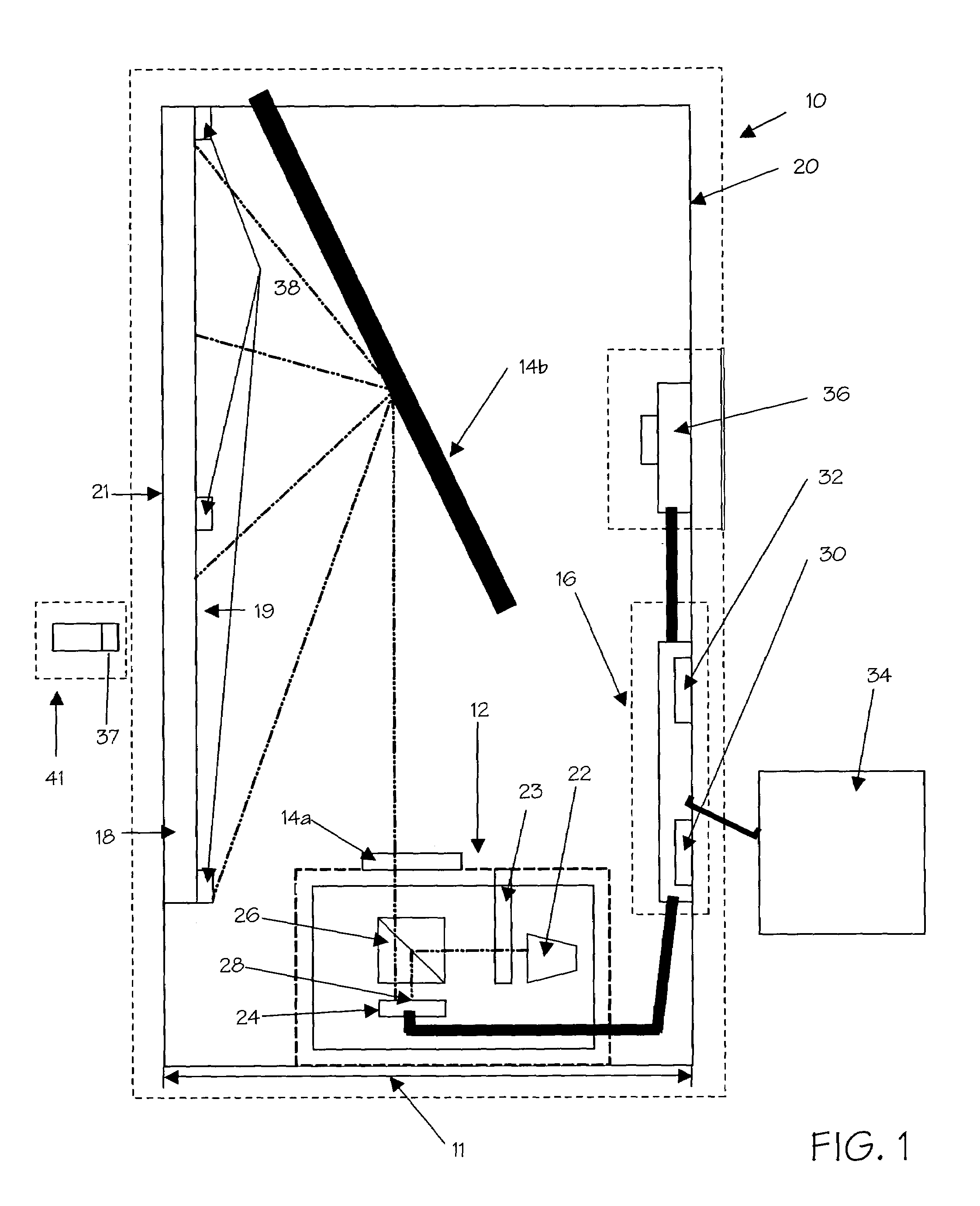
[0018]FIG. 1 displays, in schematic form, a rear projection monitor 10. The rear projection monitor 10 comprises a projector 12, projection optics 14a and 14b, control electronics 16, a viewing screen 18, and a cabinet 20. Rear projection monitor 10 is of a thin type, meaning that the depth of cabinet 20, represented by distance 11 on FIG. 1, is less than seven inches. Rear projection monitor 10 may be used, for example, as a television, a home cinema, or the like. Projector 12 is mounted below the center horizontal axis of viewing screen 18 and projects upwards, off-axis. The illustrated projector is a single microdisplay projector for use in a rear projection imaging system and includes lamp 22, spinning color wheel 23, liquid crystal on silicon (LCOS) microdisplay 24, and polarizing beam splitter 26. A multiple microdisplay projector or a field sequential color microdisplay projector that may not require the use of a spinning color wheel, as well as projectors utilizing other mic...


PUM


Abstract

A rear projection imaging system with an image warping distortion correction system using a camera and processing unit to generate a warping map that corrects for image distortion. The warping map is generated in an iterative process by displaying a known pattern on a viewing screen and, through the use of a camera, having a microprocessor determine the location and shape of the pattern on the screen. The microprocessor then compares the displayed image to the original reference image, calculates the distortion effects present in the projection optics, and generates a warping map.

Description

[0001]This application claims priority to U.S. Provisional Application No. 60 / 621,268, filed Oct. 22, 2004.FIELD OF THE INVENTIONS[0002]The inventions described below relate the field of microdisplay-based rear projection imaging systems.BACKGROUND OF THE INVENTIONS[0003]Big screen microdisplay-based rear projection imaging systems, such as televisions and monitors, are becoming increasingly popular with consumers. This is due to their combination of lightweight, high picture quality, price, and reliability over comparable large display technologies such as cathode ray tube (CRT) based rear projection imaging systems, plasma displays, and direct view liquid crystal displays (LCD). Microdisplay based rear projection imaging systems work by shining a light on single or multiple microdisplays (also known as imagers or light-valves) where an image is displayed. Microdisplays create this image by electronically turning “on” or “off” specific pixels within an array of pixels on the microd...

Claims


Application Information

Patent Timeline
Patent Type & Authority Patents(United States)
IPC IPC(8): H04N3/23H04N9/31
CPCG03B21/625G03B21/10
Inventor MCDOWALL, IAN E.BOLAS, MARK T.
Owner FAKESPACE LABS
Why Eureka
Try Eureka