
Elastomeric CMOS based micro electromechanical varactor

a micro electromechanical and cmos-based technology, applied in the field of microelectromechanical system (mems) variable capacitors, can solve the problems of limited maximum capacitance tuning range achieved by parallel plate electrode approaches, drastic reduction in reliability, and increased processing complexity, so as to increase the overall sidewall area and increase the capacitance density

Inactive Publication Date: 2007-09-04
IBM CORP
View PDF9 Cites 25 Cited by
  • Summary
  • Abstract
  • Description
  • Claims
  • Application Information

AI Technical Summary

Benefits of technology

The invention is about a MEMS variable capacitor that can withstand stresses that may cause the separation of dielectric material from the conductive elements of the device. The capacitor has a controlled stress gradient that leads to an initial curvature of the movable electrodes, which increases the overall sidewall area and capacitance density. The movable electrodes are formed by fabricating series of metal lines with interconnecting vias, and elastomeric material is embedded between the vias to improve the performance of the capacitor. The method of fabricating the capacitor involves depositing layers of dielectric and metal, etching cavities, and filling the cavities with sacrificial material. The invention provides a reliable and efficient MEMS variable capacitor that can withstand stresses and has improved capacitance density.

Problems solved by technology

Researchers have attempted to improve the tuning range of MEMS variable capacitors since the maximum capacitance tuning range achieved by using a parallel plate electrode approach is limited.
Most previous approaches have resulted in an increased processing complexity and / or a large number of moving parts, leading to a drastic reduction in reliability.
Additionally, packaging the MEMS device and integrating it into CMOS integrated circuit pose great challenges.
Even though the tuning range significantly improves when using this approach, the process complexity increases correspondingly.
This approach is expected to produce a very large tuning range, but it involves fabricating the device on two separate substrates.
Further the device is a three port varactor device and does not offer multiple modes of actuation for enhancing the tuning range of the device.

Method used


Image

  • Elastomeric CMOS based micro electromechanical varactor
  • Elastomeric CMOS based micro electromechanical varactor
  • Elastomeric CMOS based micro electromechanical varactor

Examples


Embodiment Construction

[0028]The present invention will now be described more fully hereinafter with reference to the drawings, in which preferred embodiments are shown.

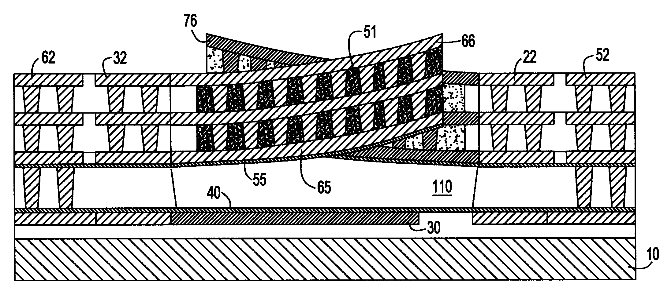
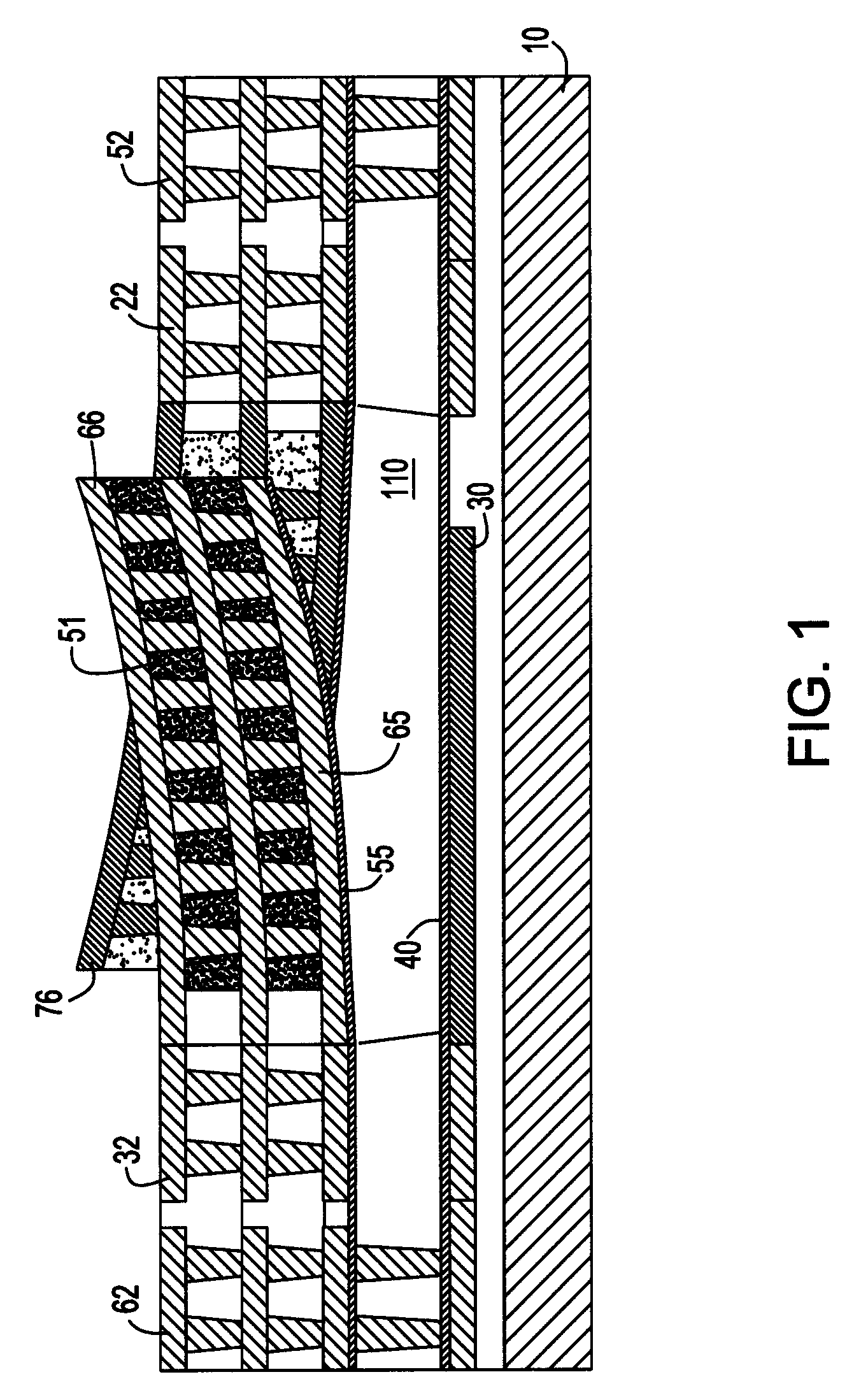
[0029]Referring to FIG. 1, there is shown a cross section view of the micro electromechanical system (MEMS) variable capacitor, in accordance with the invention. The device is built on a substrate 10 upon which movable electrodes 76 and 66 and fixed electrode 30 are sequentially constructed using conventional semiconductor fabrication techniques. The electrodes 76 and 66 are built in a comb-drive electrode configuration wherein one end of the comb-drive finger is fixed in space, while the second is free to move, as described in patent application Ser. No. 10 / 710,283. The capacitance of the varactor is determined by the overlap sidewall area between the two electrodes (i.e., the metal in one movable electrode facing the corresponding metal in the second) and the spacing between the two electrodes. Electrodes 76 are preferably made of multi-...


PUM


Abstract

A micro electro-mechanical system (MEMS) variable capacitor is described, wherein movable comb electrodes of opposing polarity are fabricated simultaneously on the same substrate and are independently actuated. The electrodes are formed in an interdigitated fashion to maximize capacitance. The MEMS variable capacitor includes CMOS manufacturing steps in combination with elastomeric material selectively used in areas under greatest stress to ensure that the varactor will not fail as a result of stresses that may result in the separation of dielectric material from the conductive elements. The combination of a CMOS process with the conducting elastomeric material between vias increases the overall sidewall area, which provides increased capacitance density.

Description

CROSS-REFERENCE TO RELATED APPLICATIONS[0001]This application is related to patent application Ser. No. 10 / 710,283, Micro Electro-Mechanical Variable Capacitor, filed concurrently, and which is incorporated herein by reference.BACKGROUND OF INVENTION[0002]This invention is generally related to a micro-electromechanical system (MEMS) variable capacitor and, more particularly, to a method of fabricating an elastomeric MEMS varactor which can be fully integrated in current state of the art semiconductor fabrication processes.[0003]Variable capacitors or varactors play a fundamental role in high-frequency and radio-frequency (RF) circuits. In the last few years, MEMS variable capacitors have drawn considerable interest due to their superior electrical characteristics. Variable capacitors using MEMS technology can be easily implemented in standard semiconductor devices for applications in aerospace, consumer electronics and communications systems. Researchers have attempted to improve th...

Claims


Application Information

Patent Timeline
Patent Type & Authority Patents(United States)
IPC IPC(8): H01L21/20H01L21/4763
CPCH01G5/18H01G5/38
Inventor CHINTHAKINDI, ANIL K.SCHNURMANN, HENRI D.
Owner IBM CORP
Learn More