Reducing scale factor transmission cost for MPEG-2 advanced audio coding (AAC) using a lattice based post processing technique

a post processing technique and scale factor technology, applied in the field of reducing scale factor transmission cost for mpeg2 advanced audio coding (aac) using a lattice based post processing technique, can solve the problems of increasing the quantization noise in a particular, complicating the scale factor derivation, and reducing the scale factor, so as to reduce the total bit cost, increase the bit cost, and reduce the scale factor value

Inactive Publication Date: 2007-09-18
DOLBY LAB LICENSING CORP
View PDF7 Cites 41 Cited by
  • Summary
  • Abstract
  • Description
  • Claims
  • Application Information

AI Technical Summary

Benefits of technology

[0011]The present invention is directed to a method for reducing the total bit cost of a perceptual audio encoder employing adaptive bit allocation in which a time domain representation of an audio signal is divided into successive time blocks, each time block is divided into frequency bands, and a scale factor is assigned to each of ones of the frequency bands, wherein the number of bits required to represent each block increases with increases in the scale factor values and with increases in band-to-band variations in scale factor values. A preliminary s

Problems solved by technology

Conversely, decrementing a scale factor increases the quantization noise in a particular band by reducing the bits allocated to it.
The Huffman codes defined in the AAC standard, are such that large variations in the scale factor parameters from band to band lead to excessive consumption of the available bits in the form of side information, which complicates the scale factor derivation as explained in the next section.
Calculating the scale factors in an AAC encoder is a very difficult problem due to the uncertainty in the noise allocation achieved by altering the scale factors and the use of a non-linear quantizer stage.
The analysis-by-synthesis technique

Method used


Image

  • Reducing scale factor transmission cost for MPEG-2 advanced audio coding (AAC) using a lattice based post processing technique
  • Reducing scale factor transmission cost for MPEG-2 advanced audio coding (AAC) using a lattice based post processing technique
  • Reducing scale factor transmission cost for MPEG-2 advanced audio coding (AAC) using a lattice based post processing technique

Examples


Embodiment Construction

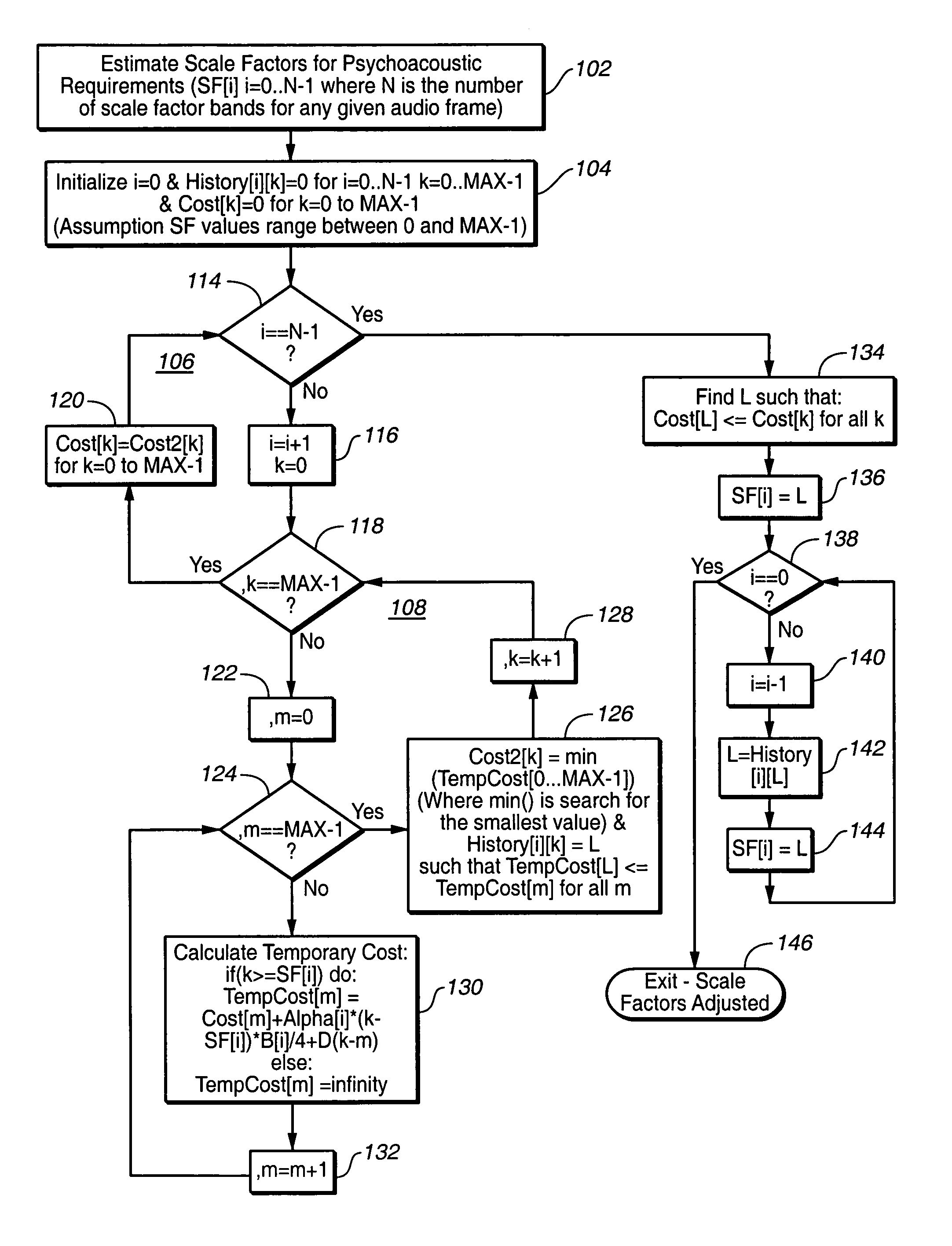
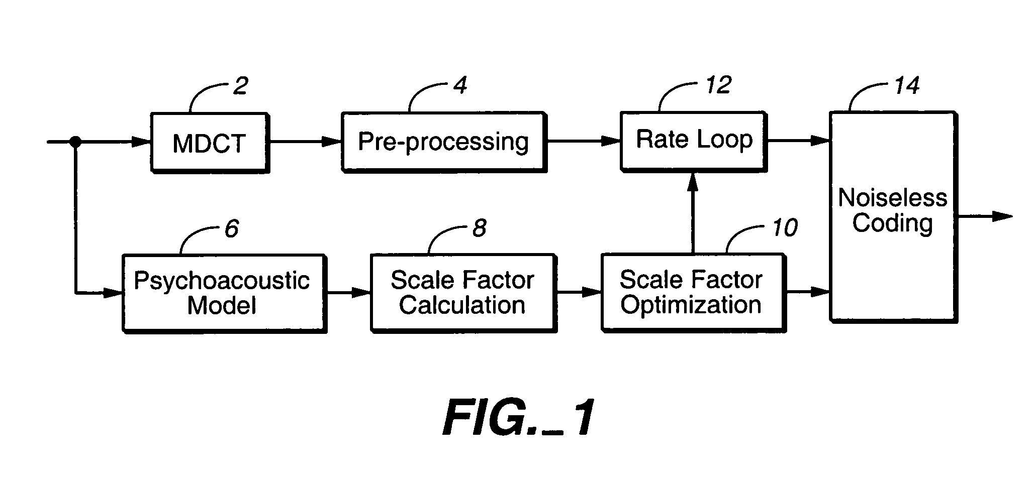
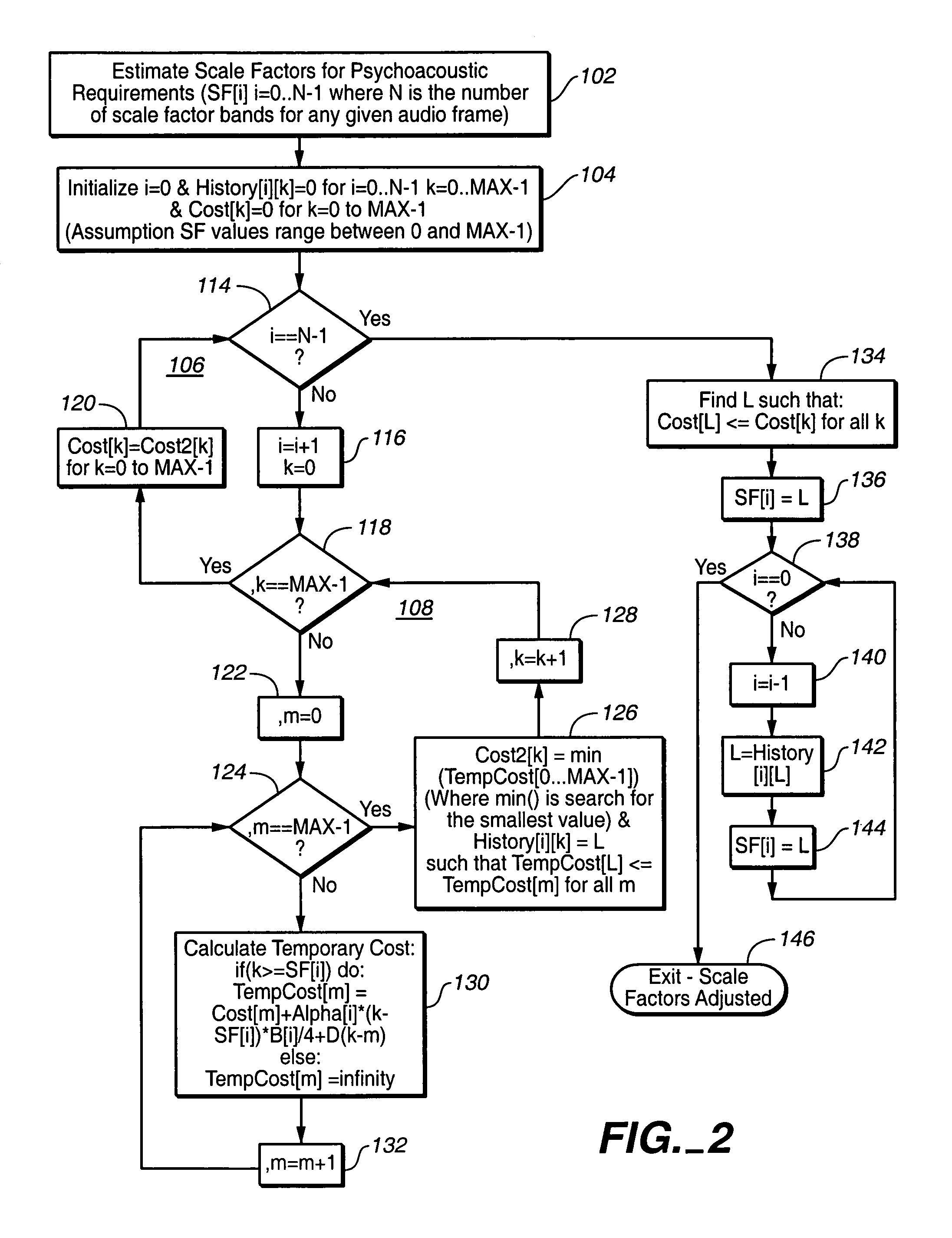
[0018]FIG. 1 shows a simple, high level schematic of an AAC encoding process incorporating dynamic programming scale factor optimization according to the present invention. The figure shows the scale factor optimization according to the present invention in conjunction with the direct scale factor estimation from masking model information described above. While other scale factor derivation techniques may be improved using the teachings of this invention, the invention is particular suitable for use with this direct estimation technique.

[0019]In FIG. 1, the input audio is transformed using an MDCT 2, followed by pre-processing 4 (e.g., temporal noise shaping (TNS), prediction and middle-side coding (MS) for stereo applications). The input is also passed to a psychoacoustic model 6, which calculates the masking level. As explained above, the masking model is used directly to compute the scale factors for each band (“scale factor calculation”8). While the preliminary scale factors der...


PUM


Abstract

A perceptual encoder divides an audio signal into successive time blocks, each time block is divided into frequency bands, and a scale factor is assigned to each of ones of the frequency bands. Bits per block increase with scale factor values and band-to-band variations in scale factor values. A preliminary scale factor for each of ones of the frequency bands is determined, and the scale factors for the each of ones of the frequency bands is optimized, the optimizing including increasing the scale factor to a value greater than the preliminary scale factor value for one or more of the frequency bands such that the increase in bit cost of the increasing is the same or less than the reduction in bit cost resulting from the decrease in band-to-band variations in scale factor values resulting from increasing the scale factor for one or more of the frequency bands.

Description

BACKGROUND OF INVENTION[0001]Typical transform and filter-bank audio coding techniques such as MPEG-1 layers 1 through 3, Dolby AC-3 (also known as Dolby Digital) (Dolby, Dolby Digital and Dolby AC-3 are trademarks of Dolby Laboratories Licensing Corporation), and MPEG-2 Advanced Audio Coding (AAC) reduce transmission data rates by dynamically allocating bits in both time and frequency to remove inaudible redundancies in the audio signal. The dynamic allocation of bits is typically based on signal dependent psychoacoustic principles. Further details of Dolby AC-3 may be found in Digital Audio Compression (AC-3) Standard. Approved Nov. 10, 1994. (Rev 1) Annex A added Apr. 12, 1995. (Rev 2) 13 corrigendum added 24, May 1995. (Rev 3) Annex B and C added 20, Dec. 1995. Further details of AAC may be found in “ISO / IEC MPEG-2 Audio Coding by Bosi et al, presented at the 101st Convention 1996 Nov. 8-11, 1996, Los Angeles, Audio Engineering Society Preprint 4382).[0002]In AAC, bit allocation...

Claims


Application Information

Patent Timeline
IPC IPC(8): G10L19/00G10L19/02
CPCG10L19/035
Inventor VINTON, MARK STUART
Owner DOLBY LAB LICENSING CORP
Why Eureka
Try Eureka