Tuning fork gyroscope

Inactive Publication Date: 2005-03-08
CHARLES STARK DRAPER LABORATORY
View PDF11 Cites 18 Cited by
  • Summary
  • Abstract
  • Description
  • Claims
  • Application Information

AI Technical Summary

Benefits of technology

It is a further object of this invention to provide such a tuning fork gyroscope which reduces the sensitivity of the scale factor to acceleration.
It is a further object of this invention to provide such a tuning fork gyroscope with increased scale factor and improved sensitivity.
It is a further object of this invention to provide such a tuning fork gyroscope with improved bias magnitude and stability.
It is a further object of this invention to provide such a tuning fork gyroscope which is not dependent on precise manufacturing tolerances and which exhibits improved sensitivi

Problems solved by technology

Unfortunately, steady state acceleration or gravitational inputs in a direction perpendicular to the plane of the substrate causes both proof masses to move away from the substrate resulting in a scale factor error since the output signal depends on the extent of the air gap between the proof masses and the substrate.
Moreover, tuning fork gyroscopes exhibit bias errors as a result of the motor comb drives imparting forces on the proof masses along the sensing axis.
However, the motor drive to sense axis coupling causes two types of bias errors.
A second err

Method used


Image

  • Tuning fork gyroscope
  • Tuning fork gyroscope
  • Tuning fork gyroscope

Examples


Embodiment Construction

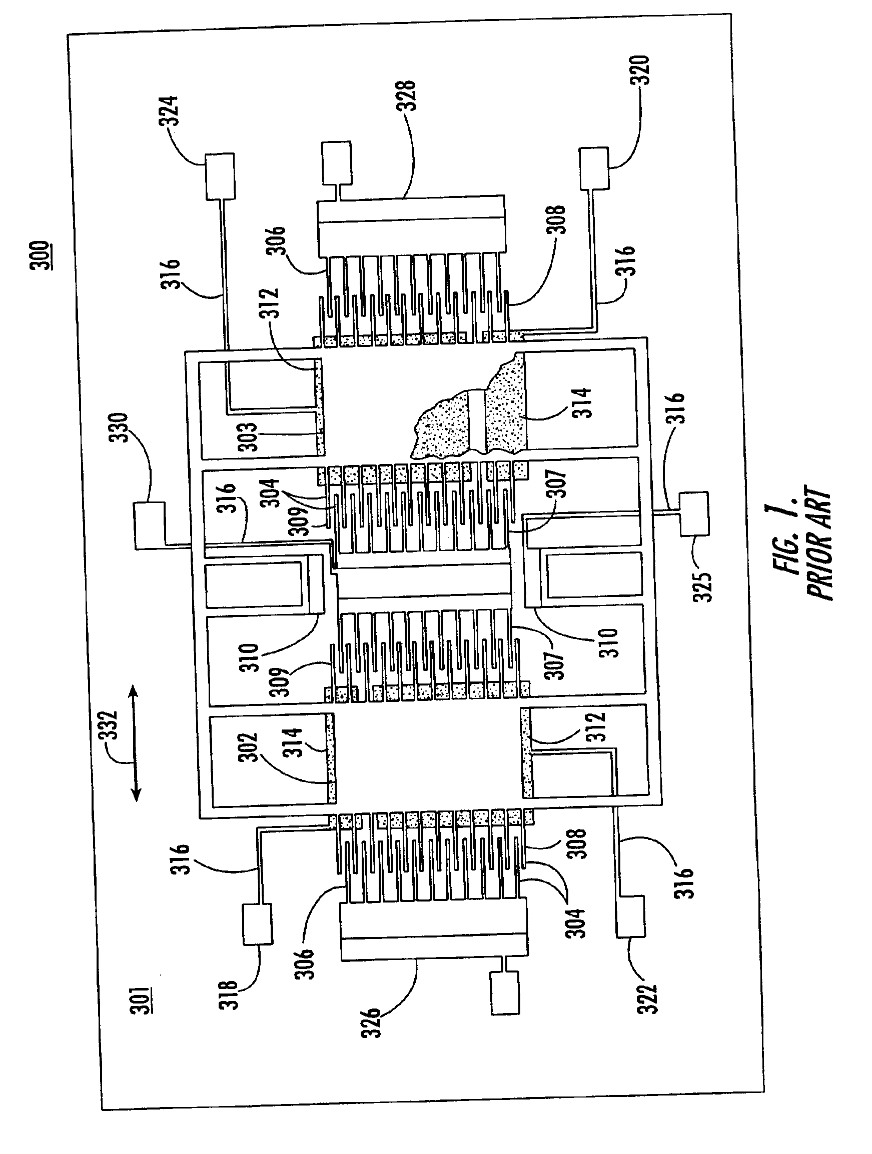
Prior art tuning fork gyroscope 300, FIG. 1, is also known in the art as a comb drive gyroscope. Gyroscope 300 includes vibrating or proof masses 302 and 303. Interleaved fingers 304, including outer comb drive fingers 306, 307 and inner comb driven fingers 308, 309 impart vibrational motion to vibrating masses 302, 303. The sensed motion is wired to electronics (not shown) that generate the driving voltage so that a self-oscillator is realized. It is known to reverse the role of inner and outer combs. Both solid and horizontally and vertically split inner combs have been used although horizontal splits in both the inner and outer combs are now preferred. Vibrating masses 302, 303 are suspended relative to lower substrate 301 by one or more anchors 310. Sense plates or electrodes 312, 313 and torque electrodes 314 are disposed only beneath a portion of each vibrating mass 302, 303. A plurality of conductive leads 316 interconnect right torque transducer 318, left torque transducer 3...


PUM

PropertyMeasurementUnit
Currentaaaaaaaaaa
Electric potential / voltageaaaaaaaaaa
Sensitivityaaaaaaaaaa

Abstract

A tuning fork gyroscope typically including at least one proof mass with an upper sense plate disposed above the proof mass and a lower sense plate disposed below the proof mass and means for sensing changes in the nominal gaps between the sense plate and the proof mass and for outputting a signal indicative of the gyroscope angular rate.

Description

FIELD OF THE INVENTIONThis invention relates to a tuning fork gyroscope.BACKGROUND OF THE INVENTIONTuning fork gyroscopes are used to sense angular displacement in military and commercial (e.g., automotive) environments. In one design, two silicon proof masses (vibrating elements) are suspended above a silicon or glass substrate (or a glass substrate with a silicon layer thereon) and there is a conductive (e.g., metal) sense plate (electrode) on the substrate under each proof mass. The inner and outer edges of each proof mass include combs or electrode fingers. Between the proof masses and adjacent to the outer edge of each proof mass are drive motors and sensors with complementary combs or electrode fingers interleaved with the combs of the two proof masses for oscillating the proof masses along a drive axis, i.e., in the direction of the plane of the substrate. Torque and sense transducers are disposed on the substrate as are conductive leads which interconnect the sense plates, t...

Claims


Application Information

Patent Timeline
IPC IPC(8): B81C1/00B81B3/00G01C19/56H01L21/683H01L21/67G01C19/5719
CPCG01C19/5719H01L21/6835H01L2924/3025H01L2924/30105H01L2924/19041
Inventor WEINBERG, MARC S.KOUREPENIS, ANTHONY S.SAWYER, WILLIAM D.BORENSTEIN, JEFFREY T.CONNELLY, JAMES H.DUWEL, AMY E.LENTO, CHRISTOPHER M.COUSENS, JAMES R.
Owner CHARLES STARK DRAPER LABORATORY
Why Eureka
Try Eureka