Eureka AIR delivers breakthrough ideas for toughest innovation challenges, trusted by R&D personnel around the world.

Method of forming a capacitor in a semiconductor device without wet etchant damage to the capacitor parts

a technology of capacitors and semiconductor devices, applied in the direction of capacitors, basic electric elements, electrical appliances, etc., can solve the problems of reducing the yield rate of semiconductor devices, limiting the capacitance required for next-generation drams, and malfunctioning drams

Inactive Publication Date: 2007-09-25
SK HYNIX INC
View PDF5 Cites 8 Cited by
  • Summary
  • Abstract
  • Description
  • Claims
  • Application Information

AI Technical Summary

Benefits of technology

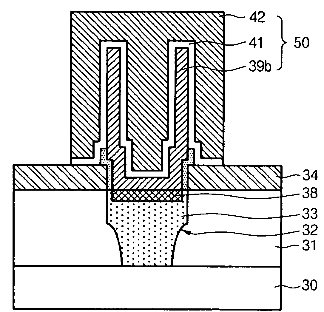
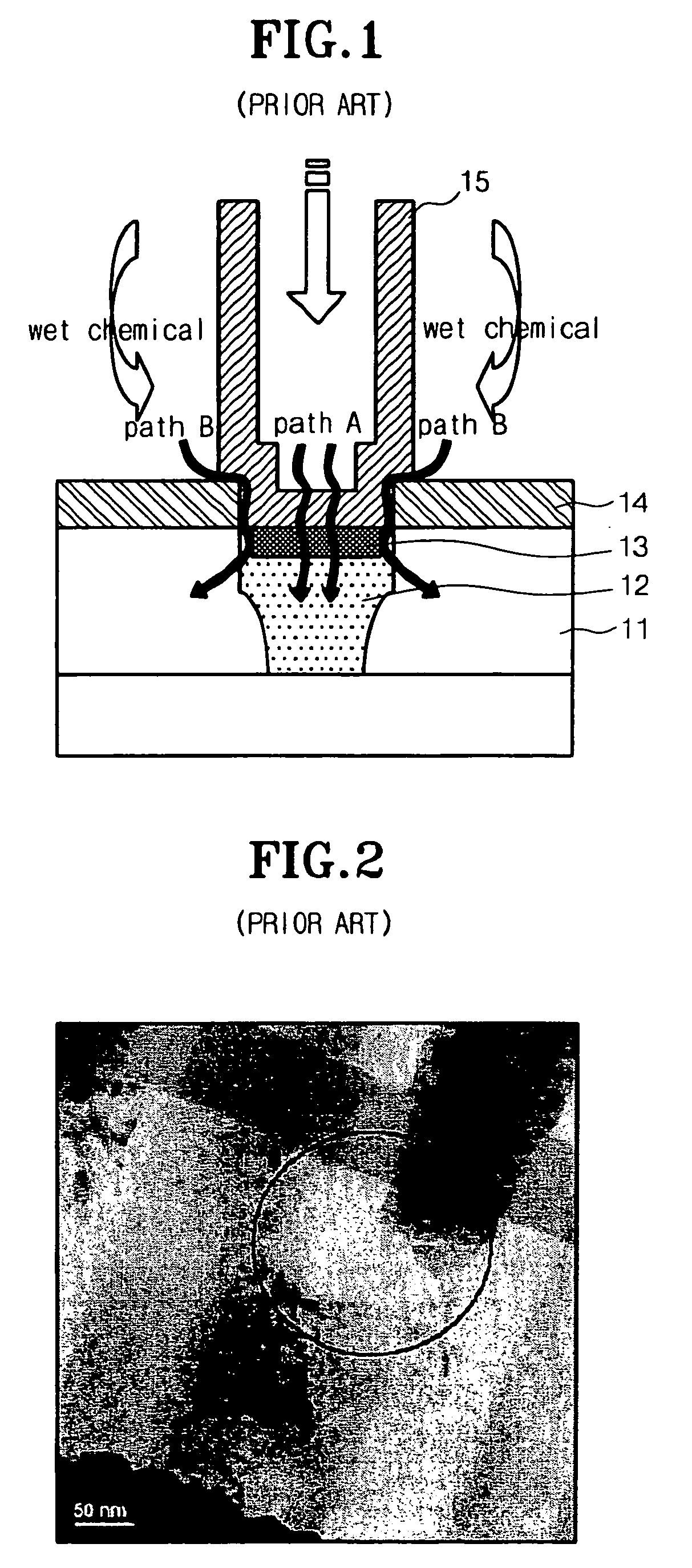
[0013]Accordingly, the present invention has been made to solve the above-mentioned problems occurring in the prior art, and an object of the present invention is to provide a method of forming a capacitor in a semiconductor device capable of preventing a contact plug damage and an interlayer insulating film loss due to wet-etch chemical penetration when a TiN layer or a Ru layer is used as a storage electrode material.
[0014]Another objective of the present invention is to provide a method of forming a capacitor in a semiconductor device with improved yield rate and reliability by preventing a contact plug damage and an interlayer insulating film loss due to wet-etch chemical penetration through the capacitor storage electrode.
[0025]The method further comprises a step of forming a protective layer after forming the plate electrode for ensuring structural stability of the capacitor.

Problems solved by technology

Under the above circumstance, an SIS (silicon-insulator-silicon) capacitor employing a dielectric layer made from Al2O3 presents limitations for ensuring the capacitance required for next-generation DRAMs above 512M.
However, if the cylinder type capacitor is fabricated by using the TiN layer or the Ru layer as a storage electrode material, following problems may occur.
Such a defect leads to an electric connection error causing malfunction of DRAMs and reduces a yield rate of semiconductor devices because the defect may occur over the whole area of a wafer, so that it is necessary to remove the defect.

Method used


Image

  • Method of forming a capacitor in a semiconductor device without wet etchant damage to the capacitor parts
  • Method of forming a capacitor in a semiconductor device without wet etchant damage to the capacitor parts
  • Method of forming a capacitor in a semiconductor device without wet etchant damage to the capacitor parts

Examples


Embodiment Construction

[0031]Hereinafter, the present invention will be described with reference to accompanying drawings.

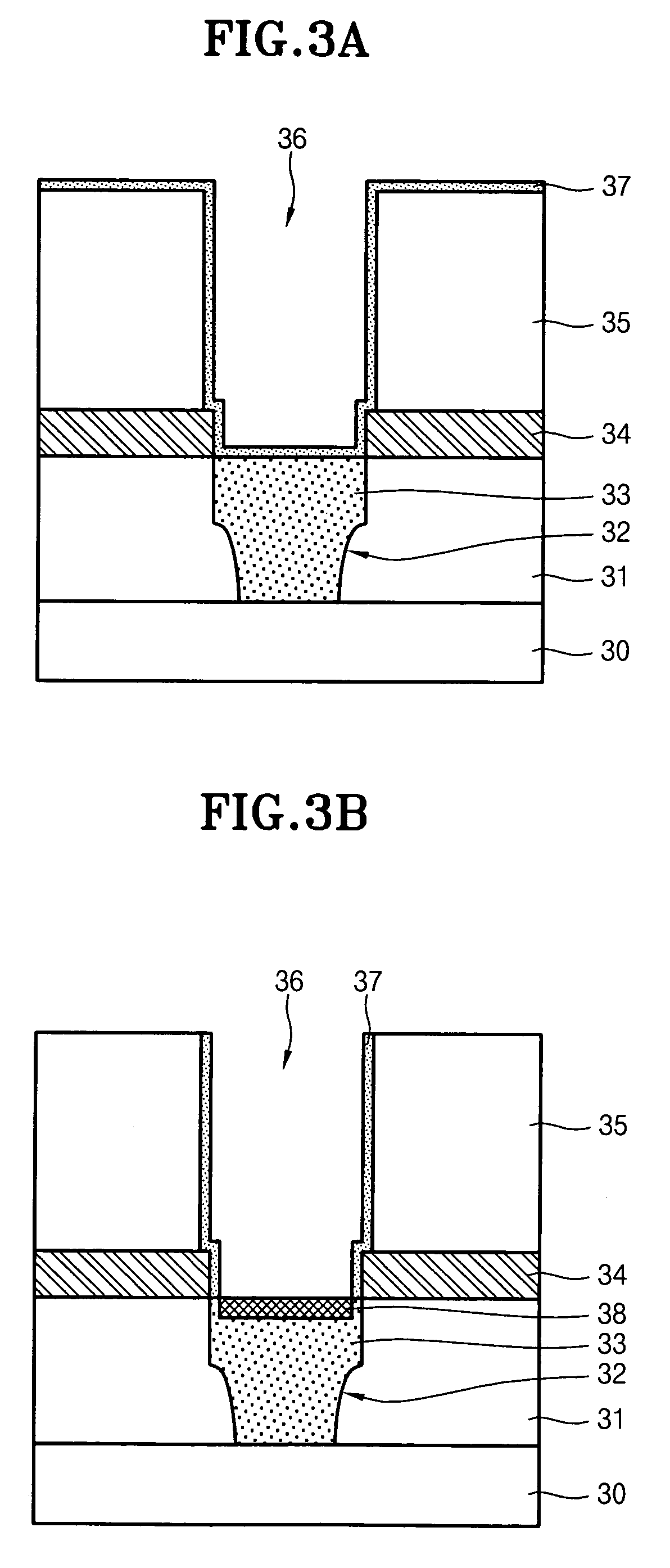
[0032]First, the technical principle of the present invention will be described. According to the present invention, a contact plug and an interlayer insulating film aligned below a storage electrode are prevented from being damaged or broken when a wet etching process is performed to remove a mold insulating layer by using an etching selectivity. That is, according to the present invention, a dielectric layer, such as Al2O3, HfO2, TiO2, Ta2O5, ZrO2 or La2O3, having a shallow thickness and a wet etching rate lower than that of an oxide layer used as a mold insulating layer, such as TEOS, PSG, BPSG or USG, is deposited after / before depositing a TiN layer or a Ru layer as a storage electrode material, thereby preventing or restricting penetration of the wet-etch chemical when the wet etching process is performed to remove a mold insulating layer. Thus, the contact plug and the interlayer...


PUM

PropertyMeasurementUnit
capacitanceaaaaaaaaaa
areaaaaaaaaaaa
equivalent oxide thicknessaaaaaaaaaa

Abstract

To form a capacitor in a semiconductor device, an etching barrier layer and a mold insulating layer are sequentially formed on an interlayer insulating film having a contact plug. A hole exposing the contact plug is formed by etching the mold insulating layer and the etching barrier layer. A first blocking layer having a wet etching rate lower than that of the mold insulating layer is formed on the hole sidewall. A storage electrode and a second blocking layer made from the identical material of the first blocking layer are formed on the resultant structure. The predetermined portions of the second blocking layer and the metal layer formed on the mold insulating layer are removed. A cylinder type storage electrode is formed by wet etching the mold insulating layer. A dielectric layer is formed on the cylinder type storage electrode. A plate electrode is formed on the dielectric layer.

Description

BACKGROUND OF THE INVENTION[0001]1. Field of the invention[0002]The present invention relates to a method of forming a capacitor in a semiconductor device. More particularly, the present invention relates to a method of forming a capacitor in a semiconductor device capable of preventing contact plug damage and interlayer insulating film loss aligned below a storage electrode due to penetration of etchant when a TiN layer or a Ru layer is used as a storage electrode material.[0003]2. Description of the Prior Art[0004]Due to the rapid advancement of the semiconductor technologies, the semiconductor memories recently produced are more likely to be highly integrated to reduce the unit cell area and to lower the operational voltage of the semiconductor devices. However, even when the cell area is reduced, a sufficient capacitance above 25 fF / cell is required for a memory device in order to prevent the refresh time from being shortened without soft error.[0005]Under the above circumstance...

Claims


Application Information

Patent Timeline
Patent Type & Authority Patents(United States)
IPC IPC(8): H01L21/8242
CPCH01L28/91H10B99/00
Inventor LEE, KEE JEUNG
Owner SK HYNIX INC
Why Eureka
Eureka Blog
Learn More