
Network switch with packet scheduling

a network switch and packet scheduling technology, applied in data switching networks, time-division multiplexing selection, digital transmission, etc., can solve problems such as packet switching that cannot eliminate packet switching cannot guarantee data delivery within limits, and packet switching cannot eliminate packet switching problems such as packet collisions and variable packet delays, so as to ensure packet delivery and reduce transmission problems , the effect of reducing the performance of other packet traffi

Inactive Publication Date: 2007-09-25
AVAYA INC
View PDF33 Cites 31 Cited by
  • Summary
  • Abstract
  • Description
  • Claims
  • Application Information

AI Technical Summary

Benefits of technology

[0024]In accordance with principles of the invention, a packet switch is disclosed herein that is capable of allocating bandwidth to each one of multiple real-time applications such that packet delay is controlled and guaranteed packet delivery is provided. The disclosed switch provides dynamic bandwidth allocation which alleviates transmission problems caused by bandwidth contention. The disclosed system allocates bandwidth for use during respective real-time communication sessions. Operation of the disclosed dynamic bandwidth allocation system does not degrade the packet switching performance of other packet traffic except to the extent that available bandwidth on the affected ports is decreased.
[0032]Negotiation or coordination with the last switch in the path is not required of the host receiver. The last switch in the path only sends the host receiver packets according to the packet flow schedule(s) associated with that host receiver. Since the host receiver receives all of its packets from the last switch in the path, that same switch will control the delivery of all packets to that receiver. Thus, the host receiver does not generally need to coordinate schedule information. The host receiver will always receive guaranteed bandwidth packets at the correct time. The receiver may normally derive any application timing information it needs to schedule the playing of the information contained in the real-time packets, from the packets themselves. Guaranteeing packet delivery times greatly reduces the need to maintain large packet jitter buffers, to counter jitter or even packet collision and retransmission problems. Since the receiver always receives the next packet in the sequence, on time, it does not require extensive jitter buffering.

Problems solved by technology

Existing Internet packet switches typically cannot guarantee delivery of data within limits needed for high-quality voice communications.
However, packet switching does not eliminate the problems of packet collisions and variable packet delays.
Such problems may occur even when a port is not fully utilized.
For example, problems may arise when multiple applications compete for a single port's resources on an instantaneous basis.
In particular, the competing applications will interfere with each other, causing variable delays to occur in the transmission or reception of one or more packets.
Unfortunately, prioritized packet processing does not improve performance in the case where all packets have equivalent priorities.
When multiple priority voice packets are mixed in a single channel, non-deterministic packet congestion and delay may result that is disruptive to a telephone call.
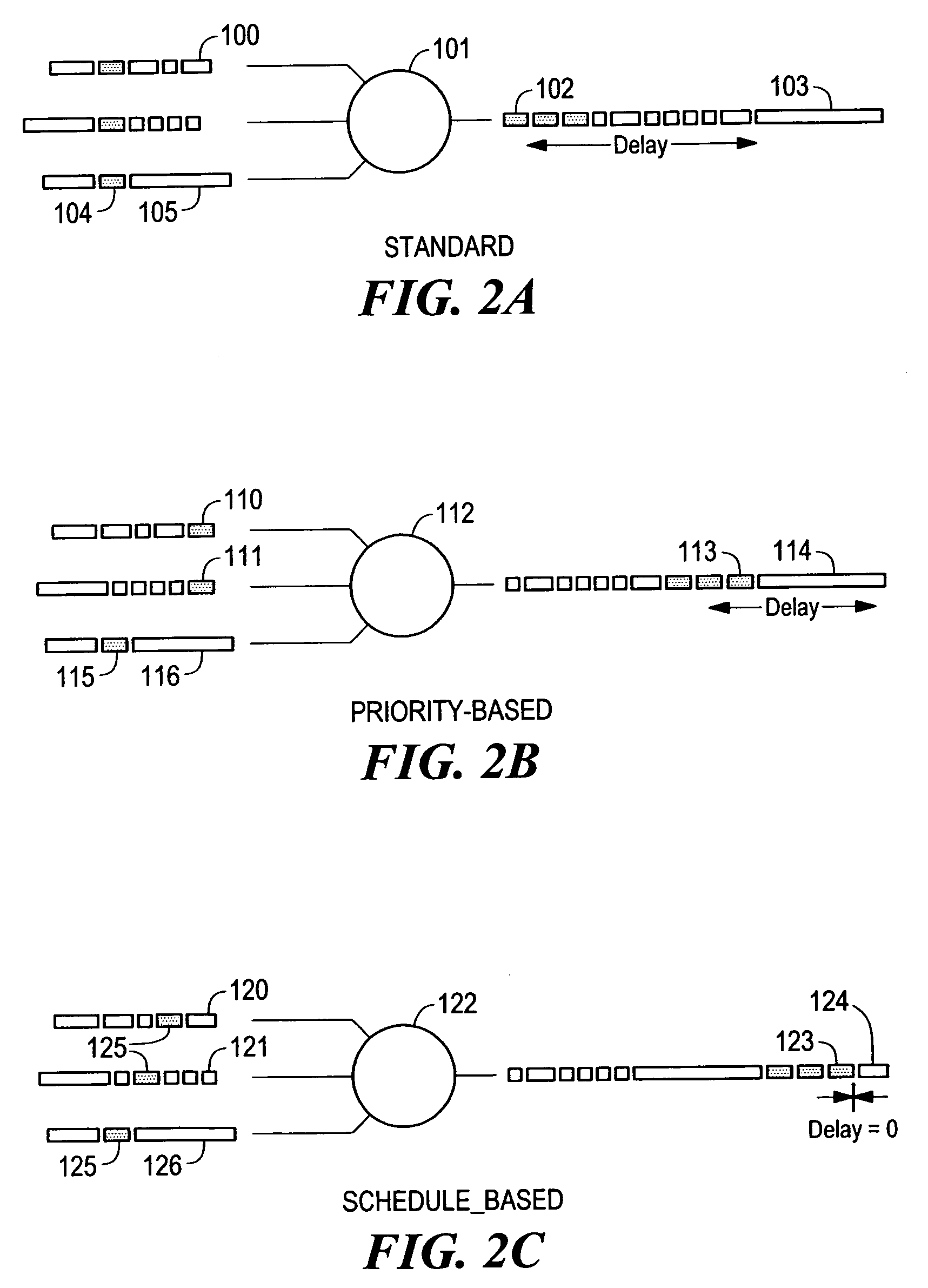
Competition for positions in the outbound data stream will result in delays, as the packets are put in queue and sent, one by one.
The actual delay will vary unpredictably between the minimum and maximum possible delays.
If the application does not buffer incoming data, then an overrun or underrun condition may result.
In the case of an underrun the momentary delay in a packet's arrival may cause the packet to be too late to be processed and played by the receiving application.
That is, the receiving application may not have data available to process when the next sample must be output.
These receive jitter buffers increase the overall system delay because packets spend time stored within the jitter buffer.
When the packet makes multiple switch and channel transitions before reaching its destination, as is normally the case, then the total delay will increase.
In fact, the average and maximum delays increase with the number of switches along a route.
Existing packet switching networks also introduce fixed delays as well as the packet insertion delays.
Such fixed delays result from a variety of causes.
First, packets experience propagation delays which depend on the physical distance over which they are transmitted.
The speed of light in free space is another fundamental limitation underlying such delays.
The resulting delay can become significant for long distance, real-time communications, especially when a packet takes a circuitous route to its destination.
For example, a principle difficulty in real-time packet communications over modems is that the insertion delay onto the relatively narrow bandwidth communications channel can be significantly high.
In addition to the delays discussed above, existing packet switching devices have their own delays.
Even in the case where the packet is high priority, and there are no queuing delays resulting from other high priority packets, the steps performed by the switch in moving the packet from queue to queue within the switch may add significant delay to the packet.
Other network packet traffic can also add delays, even if the traffic is lower in priority.
Prioritization of the packet traffic does not guarantee that high priority packets will be sent with no delay.
As a further complication, for reasons of efficiency, lower priority traffic is often aggregated into maximum length packets, thus increasing the potential delay.
On the other hand, higher priority packets are often very short, in order to lessen the insertion delay characteristics across the network.
Some networks are now transmitting “Jumbo” packets, which make the delay even longer.
This is because switching resources have limited performance in terms of the rate at which packets can be processed.
Also, transmitting and receiving hosts must be “software interrupted” to process each packet, so they too have performance limits in terms of numbers of packets processed per second.
However, Jumbo packets may wreak havoc with real-time applications, using current switch technology.
If the network channel is not sufficient to simultaneously support the total amount of bandwidth guarantees for all possible sessions, then the network is “over-subscribed”.
In this case the higher priority traffic may have adverse performance effects on the lower priority traffic.
In existing systems, there is generally no reliable means for allocating bandwidth in such a situation.
Accordingly, over-subscription can result in complete disruption of lower priority traffic, and in some cases, higher-priority traffic as well.
Unfortunately, during the call, it is completely possible for the level of congestion to grow rapidly to a point where the call is degraded or even disrupted.
Such a situation is generally intolerable for most mission critical real-time applications and particularly for voice telephony.
In this case it is not sufficient for the average traffic to be equal to or less than the bandwidth available.
Moreover, existing packet switches can easily encounter over-subscription, even where priority schemes are used.

Method used


Image

  • Network switch with packet scheduling
  • Network switch with packet scheduling
  • Network switch with packet scheduling

Examples


Embodiment Construction

[0046]The disclosures of provisional application Ser. No. 60 / 171,956, entitled “NETWORK SWITCH WITH PACKET SCHEDULING”, and filed Dec. 23, 1999, to which this application claims priority under 35 USC §119(e), are hereby incorporated by reference herein.

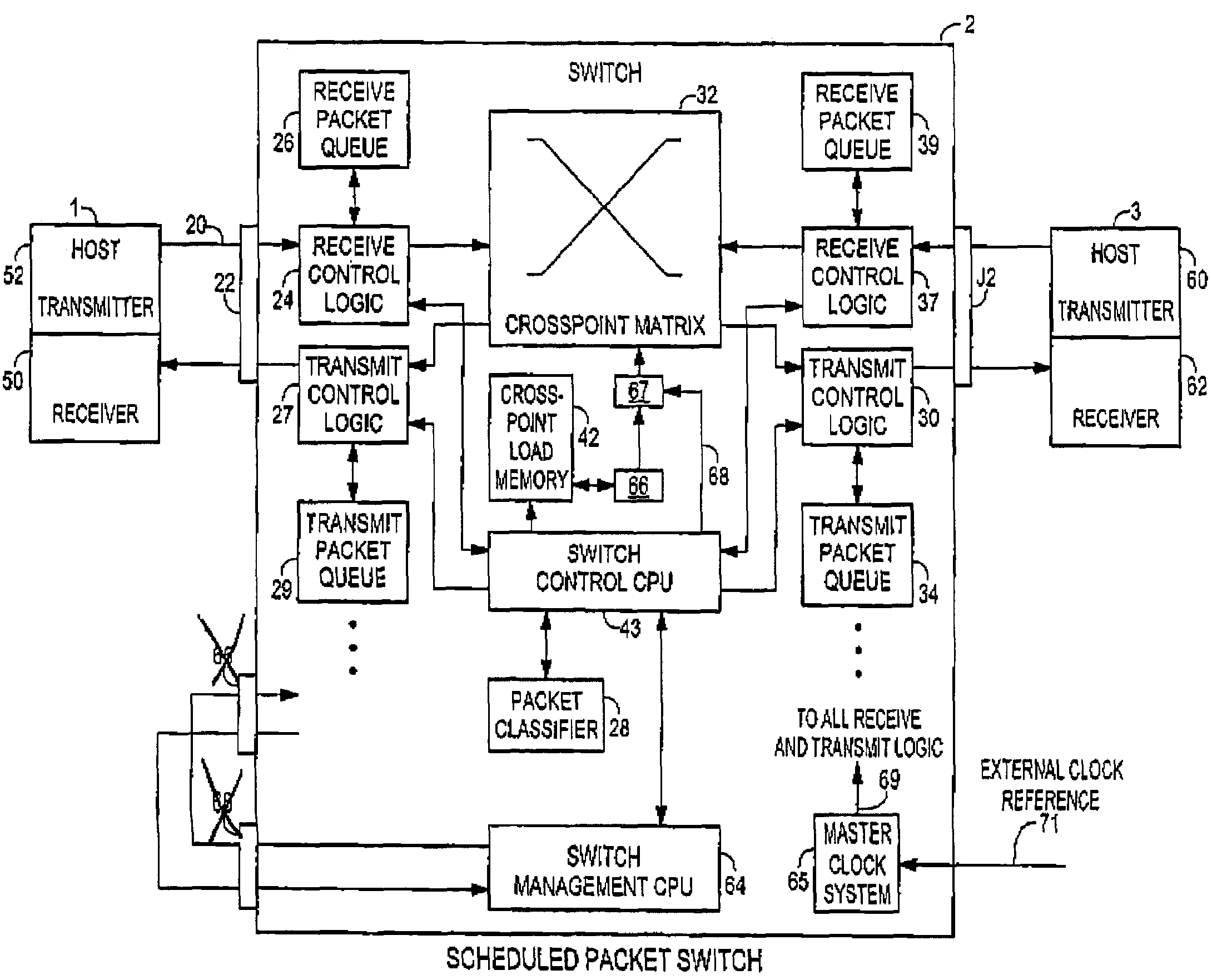
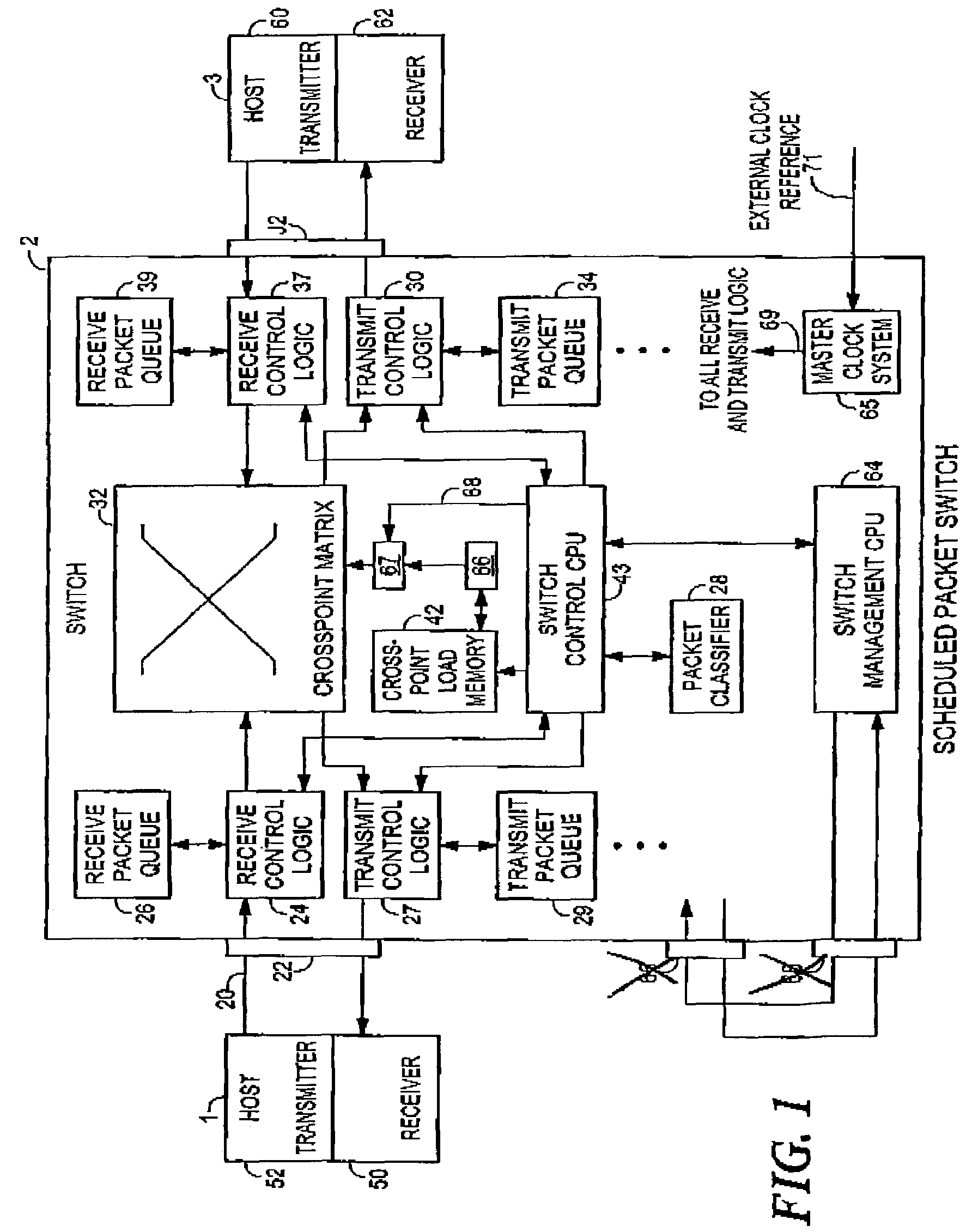
[0047]As illustrated in FIG. 1, and consistent with an illustrative embodiment of the invention, a high level block diagram of the invention shows three components: a switch 2, a first host terminal 1, and a second host terminal 3. Each of the host terminals 1 and 3 are operable to transmit and / or receive packets.

[0048]A packet which does not require guarantees in terms of delivery and / or delay is passed through the switch 2 as follows: First, the host terminal 1 transmits the packet over a communication link 20 to the switch. In the case where the host terminal 1 is interconnected to the switch 2 via an Ethernet interface, the communication link 20 may be a four pair cable, made up of UTP (Unshielded Twisted Pair) wire. However, the ...


PUM


Abstract

An apparatus and method for switching data packet flows by assigning schedules to guaranteed delay and bandwidth traffic. Scheduled bandwidth is subtracted from the available bandwidth, and the remaining unscheduled bandwidth is available for standard “best-efforts” packet transmissions, or other guaranteed packet flows. Guaranteed bandwidth is assigned on a schedule basis, and packet flows are assigned schedules which are mutually acceptable to both transmitters and receivers. Flows transmit and expect to receive packets in accordance with their assigned schedules. Schedules are negotiated between packet transmitter applications and packet receiver applications. During scheduled periods, packets sent by the packet transmitter are directly and immediately forwarded to the assigned packet receiver. Other traffic destined for the receiver is placed in a delay queue, and other packets are not transmitted to the packet receiver during the assigned schedule, as long as the transmitter is still sending guaranteed packets.

Description

CROSS REFERENCE TO RELATED APPLICATIONS[0001]This application claims priority under 35 USC §119(e) to provisional application Ser. No. 60 / 171,956, entitled “NETWORK SWITCH WITH PACKET SCHEDULING”, and filed Dec. 23, 1999.STATEMENT REGARDING FEDERALLY SPONSORED RESEARCH OR DEVELOPMENT[0002]N / ABACKGROUND OF THE INVENTION[0003]The present invention relates generally to the transmission and switching of data packets through computer networks in a manner which guarantees their delivery within bandwidth and delay limits, as is required for most real-time applications, such as voice telephony. Voice communications are one example of real time communication applications that are sensitive to data delay and to missing data, and to which the present invention may advantageously be applied. Existing Internet packet switches typically cannot guarantee delivery of data within limits needed for high-quality voice communications. To address this problem, the present invention provides a switching ...

Claims


Application Information

Patent Timeline
Patent Type & Authority Patents(United States)
IPC IPC(8): H04L12/28H04Q11/00H04L12/56H04Q11/04
CPCH04L45/40H04L47/10H04L47/2416H04L49/3081H04Q11/0478H04L2012/5651H04L2012/5679
Inventor ROGERS, STEVEN A.
Owner AVAYA INC
Learn More