Beam, ink jet recording head having beams, and method for manufacturing ink jet recording head having beams

a technology beam, which is applied in the direction of separation process, instruments, filtration separation, etc., can solve the problems of reduced mechanical strength of ink jet recording head (substrat), reduced mechanical strength of ink jet recording head, and increased length of the line in which the ejection orifice is aligned, so as to improve mechanical strength and facilitate the change

Inactive Publication Date: 2007-10-02
CANON KK
View PDF23 Cites 6 Cited by
  • Summary
  • Abstract
  • Description
  • Claims
  • Application Information

AI Technical Summary

Benefits of technology

[0017]The method, in accordance with the present invention, for manufacturing an ink jet recording head, makes it possible to satisfactorily manufacture an ink jet recording head in accordance with the present invention. Further, the shape (vertical measurement, and width of bottom) into which a beam is formed can be easily changed by changing the shape of the grooves formed in the step (e), and the shape of the grooves formed in the step (g) for forming the beams. Further, the surfaces, other than the bottom surface, of each beam, and the surfaces of the side walls of the common liquid chamber, are formed by anisotropic etching. Therefore, these surfaces are parallel to the (111) face of the crystal of which the substrate is formed, being therefore highly resistant to corrosion.
[0021]The method, in accordance with the present invention, for forming a beam makes it possible to satisfactorily form the above described beam in accordance with the present invention. It is particularly effective if it is used in a process in which a microscopically structured component is manufactured with the use of an anisotropic etching method. It is similar to the above described head manufacturing method in that the shape (vertical measurement, width of bottom, etc.) into which a beam is formed can be easily changed by changing the shape of the grooves formed in the step (a), and the shape of the grooves formed in the step (c) for forming the beams.
[0022]As described above, according to the present invention, an ink jet recording head is improved in mechanical strength by the beams formed in the common liquid chamber of the head. Therefore, the ink jet recording head is prevented from deforming, and therefore, the ejection orifices are prevented from deviating in position. Further, it is possible to manufacture reliable ink jet recording heads which are substantially longer than the ink jet recording heads in accordance with the prior art, making it therefore possible to record more precisely and at a higher speed. Further, the ink jet recording heads in accordance with the present invention are less likely to break while they are manufactured. Therefore, they are higher in yield than the ink jet recording heads in accordance with the prior art. Further, in the case of an ink jet recording head in accordance with the present invention, the opening of the ink supplying hole of the common liquid chamber faces the front side of the substrate, eliminating the problem concerning the refill time. Therefore, the ejection orifices of the ink jet recording head in accordance with the present invention are uniform in ejection frequency, enabling the ink jet recording head to record at a high speed. Further, a beam in accordance with the present invention is unlikely to be corroded from its peak by ink or the like. Therefore, it is well suited for an ink jet recording head. Further, it is also well suited for the beam for a microscopically structured component, in addition to an ink jet recording head, which is always in contact with alkaline liquid or the like, because the beam in accordance with the present invention is resistant to alkali.

Problems solved by technology

However, in order to record images more precisely and at a higher speed than the levels of precision and speed at which images are recorded by an ink jet recording apparatus in accordance with the prior art, not only must ejection orifices be increased in density, but also, the line in which ejection orifices are aligned must be increased in length, which creates a problem.
As a result, the ink jet recording head (substrate) is reduced in mechanical strength.
The reduction in the mechanical strength of the substrate causes the deformation of the substrate and / or damage to the substrate during the process for manufacturing ink jet recording heads.
This in turn makes it possible that such problems as reduction in yield, or unsatisfactory recording performance, will occur.
However, when two or more ink supplying holes were formed by literally using the method disclosed in Japanese Laid-open Patent Application 10-181032, the distances between some of the ejection orifices and corresponding ink supplying hole became different from the distances between the other ejection orifices and the corresponding ink supplying hole, because the openings of the ink supply holes on the back side of the substrate became different in size from those on the front side, reducing thereby the speed at which the ink passages were refilled with ink.
As a result, it was difficult to achieve a practical printing speed.
This method for forming a beam can be used for forming a beam narrower at the bottom, or the portion which coincides with the back surface of the substrate, but, it suffers from the problem that the inward side of the beam is dissolved from the peak of the beam, by the etchant with a high pH value used for anisotropic etching.

Method used


Image

  • Beam, ink jet recording head having beams, and method for manufacturing ink jet recording head having beams
  • Beam, ink jet recording head having beams, and method for manufacturing ink jet recording head having beams
  • Beam, ink jet recording head having beams, and method for manufacturing ink jet recording head having beams

Examples


embodiment 1

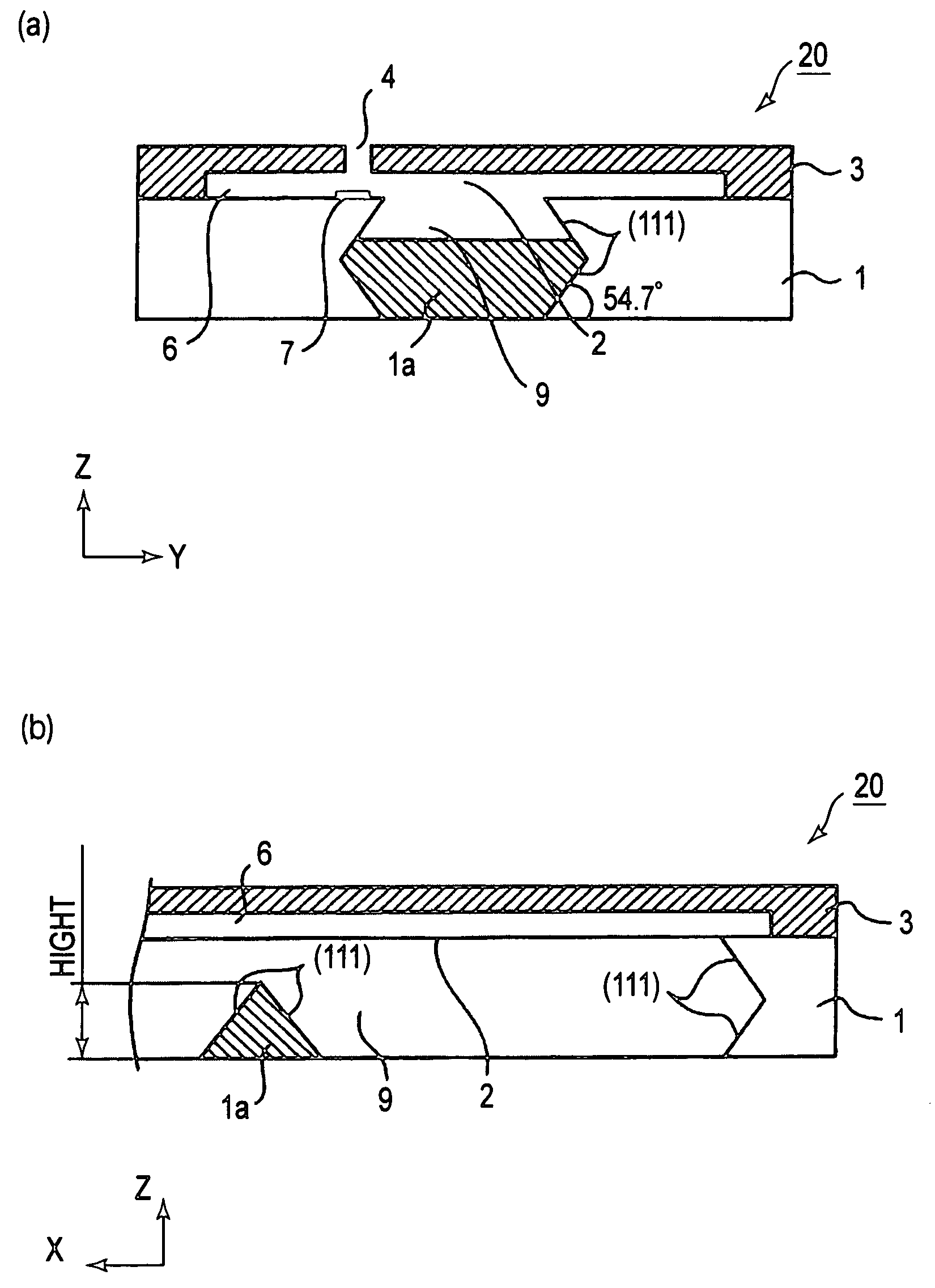
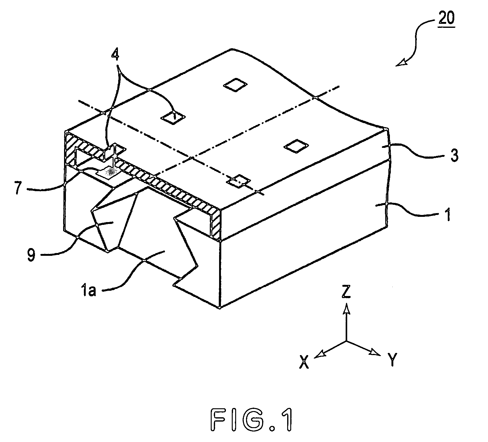
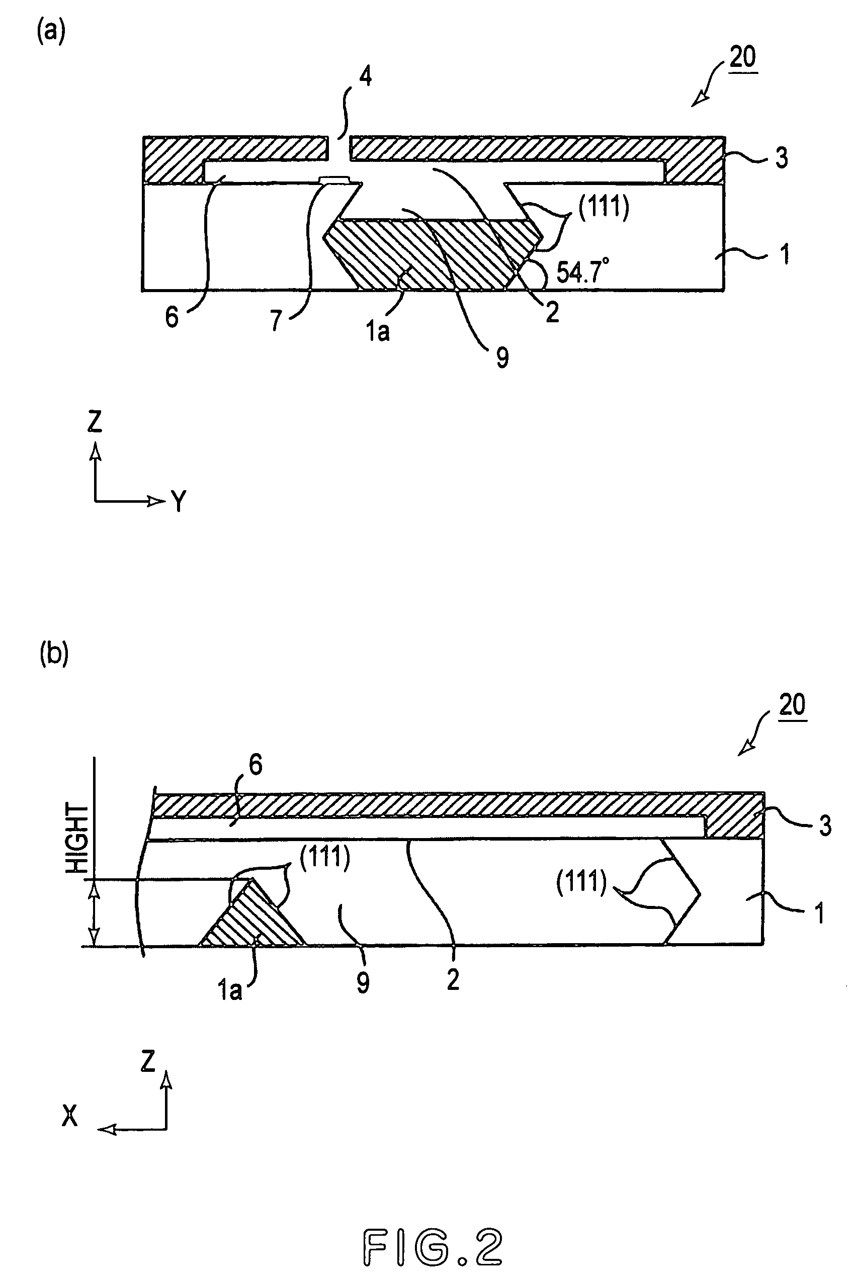
[0039]FIG. 1 is a perspective view of an example of an ink jet recording head in this first embodiment. FIG. 2 is a sectional view of the ink jet recording head shown in FIG. 1. FIGS. 2(a) and 2(b) are sectional views at planes parallel to the widthwise and lengthwise directions, respectively, of the ink jet recording head.

[0040]Referring to FIG. 1, the ink jet recording head 20 in this embodiment comprises a substrate 1 formed of a piece of a single crystal of silicon, and an orifice plate 3 having a plurality of ejection orifices and solidly glued to the substrate 1. The substrate 1 has: a common liquid chamber 9 from which ink is supplied to the ejection orifices; and a beam 1a which is on the back side of the substrate 1, being inside the common liquid chamber 9.

[0041]Referring to FIG. 2, the common liquid chamber 9 extends from one end of the substrate 1 to the other. The orientation of the side walls (internal wall) of the common liquid chamber 9 formed of a single crystal of ...

embodiment 2

[0058]Next, referring to FIGS. 6 and 7, the method for manufacturing the ink jet recording head and the reinforcement beam therefor, in the first embodiment of the present invention will be described. The manufacturing method, which will be described next, is the manufacturing method for the ink jet recording head 21 shown in FIG. 6(i).

[0059]The ink jet recording head 21 comprises a substrate 1, and an orifice plate 3 having a plurality of ejection orifices (unshown) and placed on the substrate 1, as does the ink jet recording head shown in FIGS. 1-3. The substrate 1 of the ink jet recording head 21 is provided with three reinforcement beams 1a similar in configuration to the one shown in FIG. 2(b).

[0060]The common liquid chamber 9 extends from one end of the substrate 1 to the other, and has one opening (ink supplying hole 2), which faces the front side of the substrate 1. The ink supplying hole 2 is connected to the ink passages (unshown) on the inward side of the orifice plate 3....

embodiment 3

[0093]Referring to FIG. 8, the method for manufacturing the ink jet recording head and the reinforcement beam therefor, in another embodiment of the present invention, will be described. The manufacturing method which will be described next is for the ink jet recording head (unshown) similar to the ink jet recording head 21 shown in FIG. 6(i), except that the beam protective layer 14 and projections 14a of the ink jet recording head in this embodiment are formed of silicon dioxide instead of silicon nitride. The precursor 22a shown in FIG. 8(e) is identical in configuration to the precursor 21 a shown in FIG. 6(c); the former is different from the latter only in the material for the beam protection layer 14. Thus, the manufacturing steps performed after the step for forming the beam protection layer 14 are the same as the steps performed after the step used for forming the intermediate product shown in FIG. 6(d), and therefore, they will not be described.

[0094]The process for manufa...


PUM


Abstract

A beam having a base material of silicon monocrystal and at least one projection which is integrally formed so as to be supported at least at one end thereof and which has two surfaces having an orientation plane (111), includes a bottom surface in a plane which is common with a plane of the base material; a groove penetrating from the bottom surface to a top of the projection; and a protecting member having a resistance property against a crystal anisotropic etching liquid and covering an inner wall of the groove.

Description

FIELD OF THE INVENTION AND RELATED ART[0001]The present invention relates to a beam as a microscopic structural member placed in an area which remains filled with liquid or the like, and the method for forming such a beam. In particular, it relates to such a beam that improves in mechanical strength an ink jet recording head which ejects ink to record on recording medium, the method for forming such a beam, an ink jet recording head provided with such a beam, and the method for manufacturing such an ink jet recording head.[0002]An ink jet recording method (disclosed in Japanese Laid-open Patent Application 54-51837, for example), which generates bubbles by heating ink; ejects ink by utilizing the pressure generated by the growth of the bubbles; and adheres the ejected ink to the surface of recording medium, is advantageous in that it is capable of recording at a high speed, is relatively high in image quality, and is low in noises. This recording method makes it easy to record image...

Claims


Application Information

Patent Timeline
Patent Type & Authority Patents(United States)
IPC IPC(8): B41J2/05B41J2/14B41J2/16B81B1/00
CPCB41J2/14145B41J2/1623B41J2/1628B41J2/1629B41J2/1631B41J2/1632B41J2/1634B41J2/1642B41J2/1643B41J2/1646B41J2/1603Y10T428/24612Y10T428/24562Y10T428/24331Y10T428/24479Y10T428/2457B41J2/14B41J2/16
Inventor USHIJIMA, TAKASHIYAMAZAKI, TAKEOTERUI, MAKOTOHAYAKAWA, KAZUHIRO
Owner CANON KK
Why Eureka
Try Eureka