Selective corneal aberrometry

a technology of aberrometry and selective cornea, applied in the field of surface profiling, can solve the problems of inconvenient or detracting, inconvenient insertion of foreign objects on or in the eye, and the need for time-consuming procedures, and achieve the effect of accurately representing the topography of the corneal surfa

Inactive Publication Date: 2007-10-02
JEAN BENEDIKT +2
View PDF3 Cites 8 Cited by
  • Summary
  • Abstract
  • Description
  • Claims
  • Application Information

AI Technical Summary

Benefits of technology

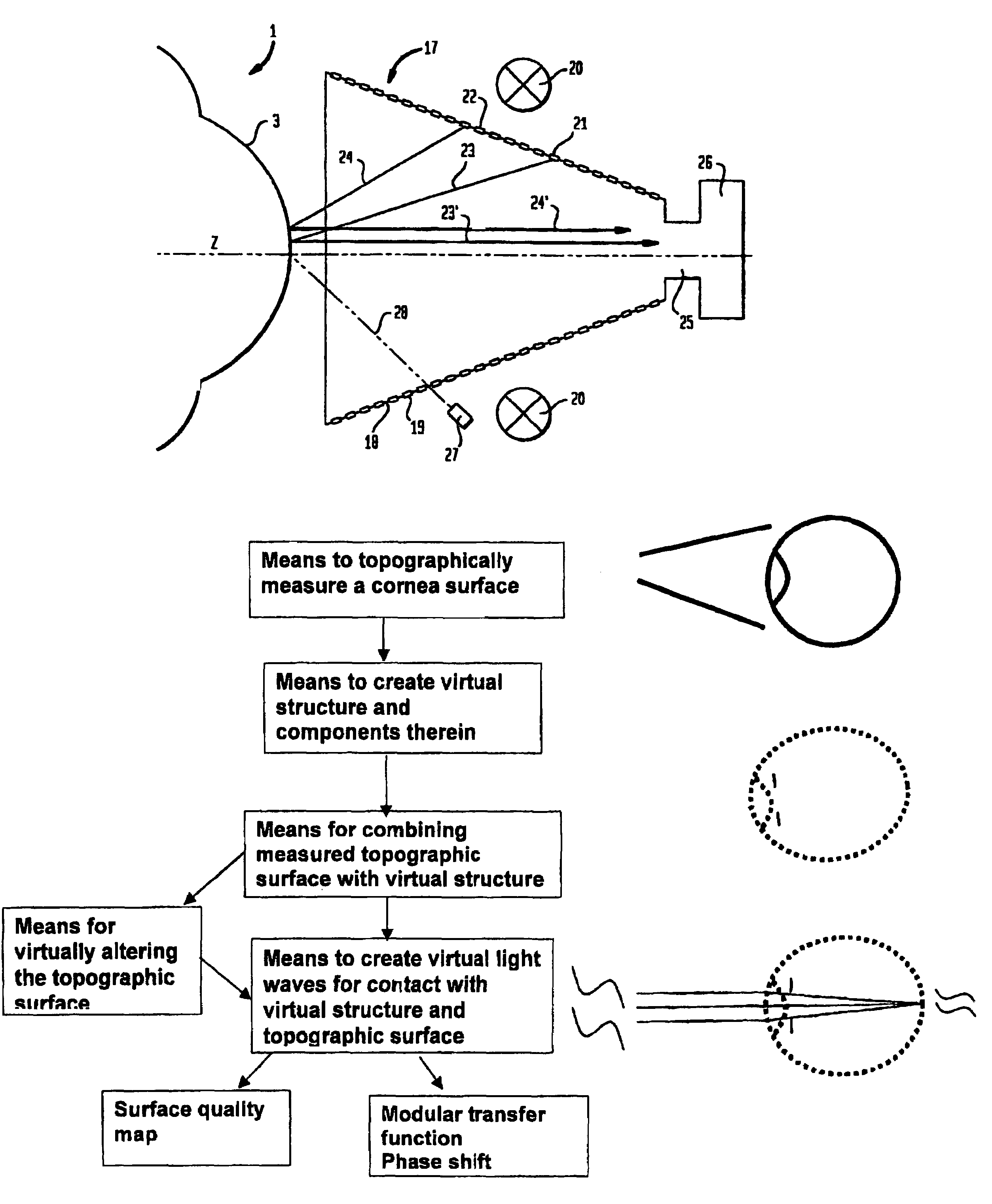
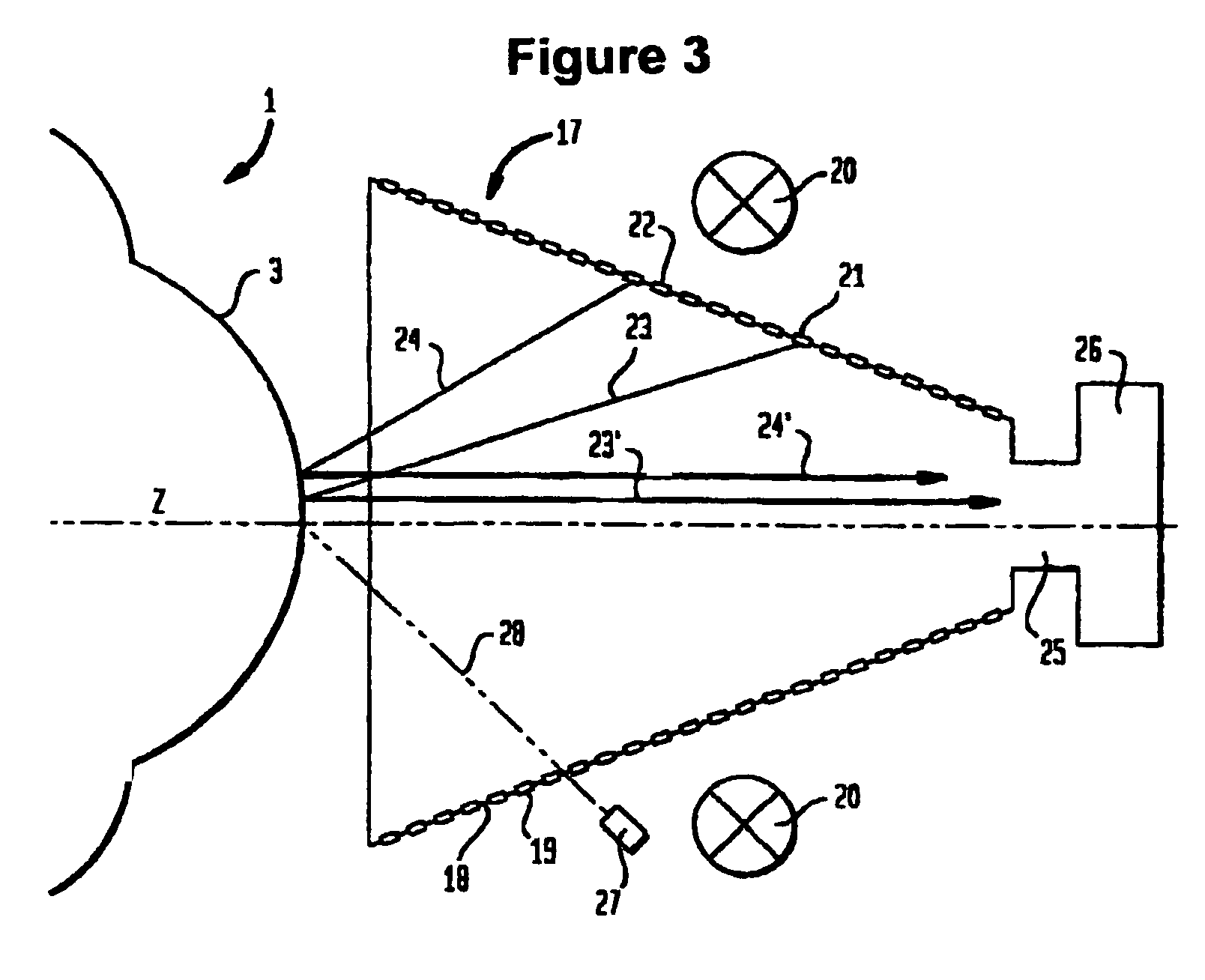
[0011]The present invention relates to a method and system for determining the surface topography of a cornea to accurately represent the topography of the corneal surface and provide guidance for permanent corneal reshaping that corrects for only corneal aberrations.

Problems solved by technology

However, glasses are worn externally and are not infrequently perceived to be uncomfortable, inconvenient, or detracting from personal appearance.
Contact lenses are sometimes utilized when the use of glasses has been considered to be undesirable, mostly for cosmetic reasons.
However, contact lenses entail problems of their own in terms of possible eye infection and the necessity for time consuming procedures required to maintain sterility and minimize contamination.
More importantly, many people cannot tolerate the insertion of foreign objects on or in their eyes.
However, systems and methods used heretofore determine total aberrations of the optical system and introduce not only corneal aberrations but also aberrations relating to variable elements within the eye, such as the crystalline lens, accommodation of the lens, and vitreous structures.
Thus, the measured dioptric values do not provide the option of differentiating aberrations caused by the variable elements from that of corneal aberrations originating on the anterior corneal surface.
As such, a corrective ablation procedure for reshaping the cornea may not adequately compensate or may over-compensate due to aberration data from the undifferentiated variables.
Further, determining the topographic surface of the cornea with today's aberrometers does not provide sufficient data to measure the entire area of the cornea because generally the aberrometers utilize only around 100 measurement points with an accuracy of ±100 μm in the x and y plane.
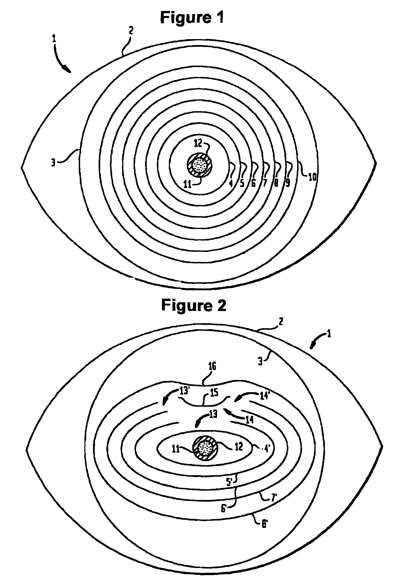
Considering that the x / y reference plane is centered about the pupilar margin, and a corneal surface is usually about 8.5 mm in diameter, there is not sufficient data to generate a topographic surface map with the necessary precession.

Method used


Image

  • Selective corneal aberrometry
  • Selective corneal aberrometry
  • Selective corneal aberrometry

Examples


example i

[0093]A standard 4.5D PRK myopia correction with an optical zone diameter of 6.5 mm, treated with an Apex plus (Summit, USA), was used to illustrate the obtained corneal aberration map (CAM), shown in FIG. 6, which combines the two graphs and surface quality map of FIG. 5. The aberration map is divided into four sub charts including, a radius map, surface quality map, contrast graph and phase shift graph. At the lower left of the CAM, the distribution of radii is shown which indicates a homogenous distribution. In the upper left of the CAM, the surface quality map shows a central dark gray area (normally a colored amp) which indicates, quantitatively, the optical aberration prevailing in a normal 20 / 20 eye having a diameter of 4.2 mm after the 4.5D PRK. The upper right graph shows “contrast” as a function of sinus wave frequencies and indicates that contrast decreases rapidly for lower frequencies. The horizontal line represent, in this graph, the physiological threshold and the int...


PUM


Abstract

A method and system are disclosed for measuring and mapping the anterior surface topography of a cornea to determine corneal aberrations and an optimal ablation pattern for refractive and therapeutic surgery of the cornea. The invention stimulates a prospective ablation process with real-time visual feedback accurately portraying results of topographic surface alteration that would occur during an actual ablation procedure, thereby achieving minimal corneal aberrations and optimal image quality.

Description

CROSS-REFERENCE TO RELATED APPLICATIONS[0001]This application is filed under the provisions of 35 USC §371 and claims the priority of International Patent Application No. PCT / EP01 / 04142 filed Apr. 11, 2001, which in turn claims priority of U.S. Provisional Patent Application No. 60 / 196,532 filed Apr. 11, 2000.BACKGROUND OF THE INVENTION[0002]1. Field of the Invention[0003]The present invention relates generally to surface profiling, and more specifically, to a method and system for measuring and mapping the anterior surface topography of a cornea to determine corneal aberrations and an optimal ablation pattern for refractive and therapeutic surgery of the cornea.[0004]2. Description of the Related Art[0005]Various methods have been developed to reshape the cornea of the human eye in order to correct for vision defects. Among these vision defects are nearsightedness (myopia), with the unaccommodated nominal focusing plane falling before the retina; farsightedness (hyperopia), with fo...

Claims


Application Information

Patent Timeline
Patent Type & Authority Patents(United States)
IPC IPC(8): A61B3/10A61B3/107A61F9/007
CPCA61B3/107A61B3/0058
Inventor JEAN, BENEDIKTBENDE, THOMASOLTRUP, THEO
Owner JEAN BENEDIKT
Why Eureka
Try Eureka