
Radiation curable resin composition

a technology of radiation curable resin and composition, which is applied in the field of coating optical fibers, can solve the problems of not providing satisfying properties with respect to cure speed, limiting the speed of production line operation, and large amount of extractables, etc., and achieves the effect of increasing the cure speed of radiation curable composition

Inactive Publication Date: 2007-10-02
COVESTRO NETHERLANDS BV
View PDF11 Cites 45 Cited by
  • Summary
  • Abstract
  • Description
  • Claims
  • Application Information

AI Technical Summary

Benefits of technology

[0028]Suprisingly, the coated optical fiber of the present invention has good properties even if produced at extremely high line speeds whereas other coated optical fibers have inferior quality. In particular, the radiation curable composition according to the present invention overcomes all the drawbacks of the prior art composition by choosing combinations and amounts of photoinitiators in such a way that an improved cure speed can be obtained without substantially deteriorating mechanical properties and yellowing characteristics (including initial yellowing and yellowing upon aging).
[0030]Finally, the present invention provides a cured coating and a method for increasing the cure speed of a radiation curable composition.

Problems solved by technology

At present, in the production of optical fibers and optical fiber assemblies, one of the limitations on how fast the production line can be operated is the cure speed of the coatings and / or binders.
So far, however, the known radiation-curable compositions also if they comprise a combination of photoinitiators in varying amounts do not provide satisfying properties with respect to cure speed in combination with mechanical and aging properties of the resulting cured coating.
Moreover, using a high amount of photoinitiator often results in drawbacks such as a relatively high amount of extractables, yellowing of the cured coating over time, and other undesired properties.

Method used


Image

  • Radiation curable resin composition
  • Radiation curable resin composition
  • Radiation curable resin composition

Examples


examples

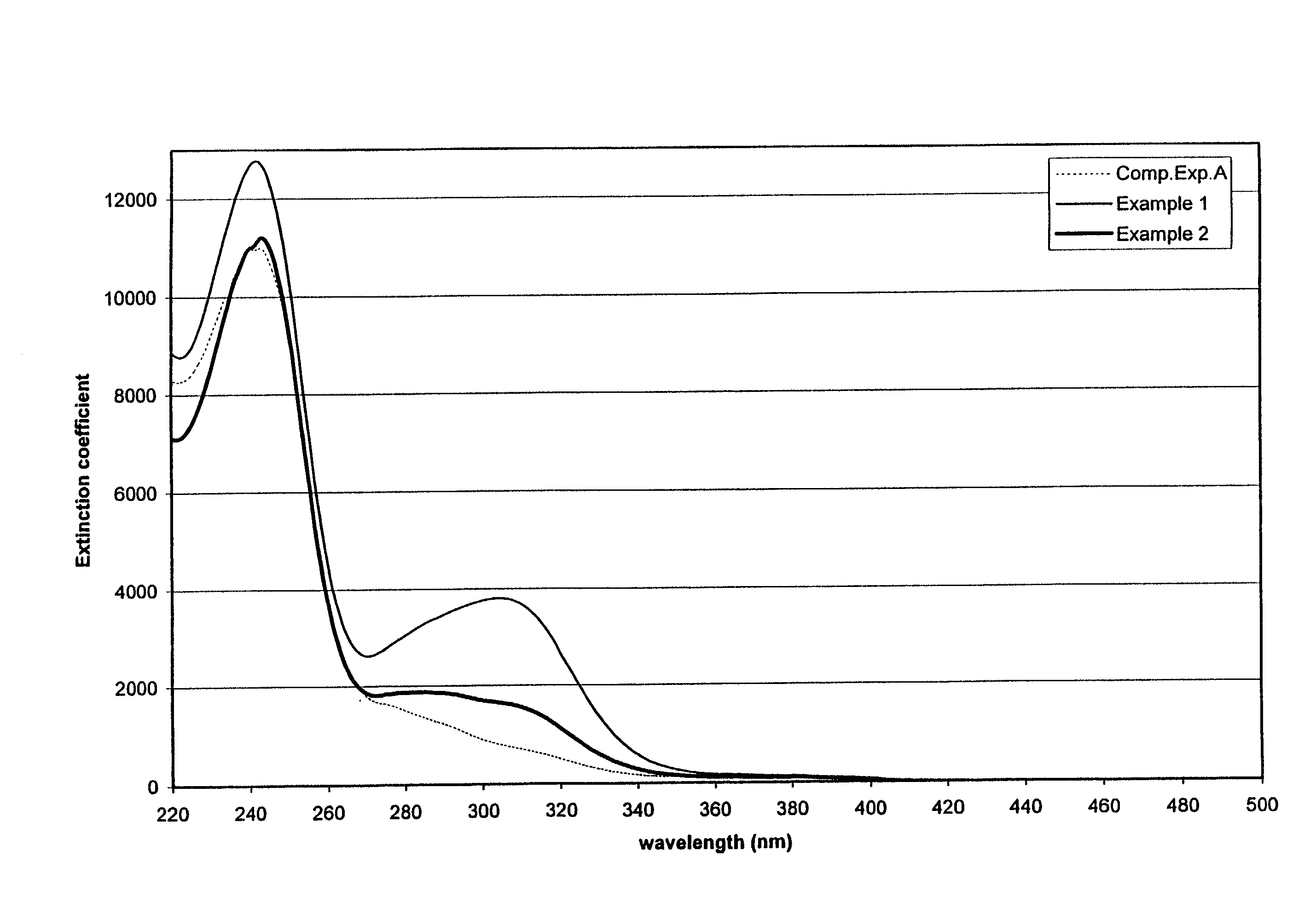
[0153]The following examples are given as particular embodiments of the invention and to demonstrate the practice and advantages thereof. The examples are given by way of illustration and are not intended to limit the specification or claims.

[0154]Radiation-curable coating compositions were prepared from a mixture of components shown in Tables 1, 2, 4, 5, and 6. These components are described below:[0155]Oligomer 1 is a polyether based urethane acrylate[0156]Oligomer 2 is a polyester based urethane acrylate[0157]Oligomer 3 is an epoxy acrylate oligomer[0158]Oligomer 4 is an alkyd based urethane acrylate[0159]Oligomer 5 is an aliphatic polyether-polycarbonate based urethane acrylate oligomer, having a Mw of 4000, which is derived from 2-hydroxyethylacrylate, isophoronediisocyanate, and equal amounts of polypropyleneglycol diol and a copolymer diol of 10-15 wt % polyether / 85-90 wt % polycarbonate.[0160]Oligomer 6 is an aliphatic polyether-polycarbonate based urethane acrylate having a...


PUM

PropertyMeasurementUnit
Fractionaaaaaaaaaa
Fractionaaaaaaaaaa
Fractionaaaaaaaaaa

Abstract

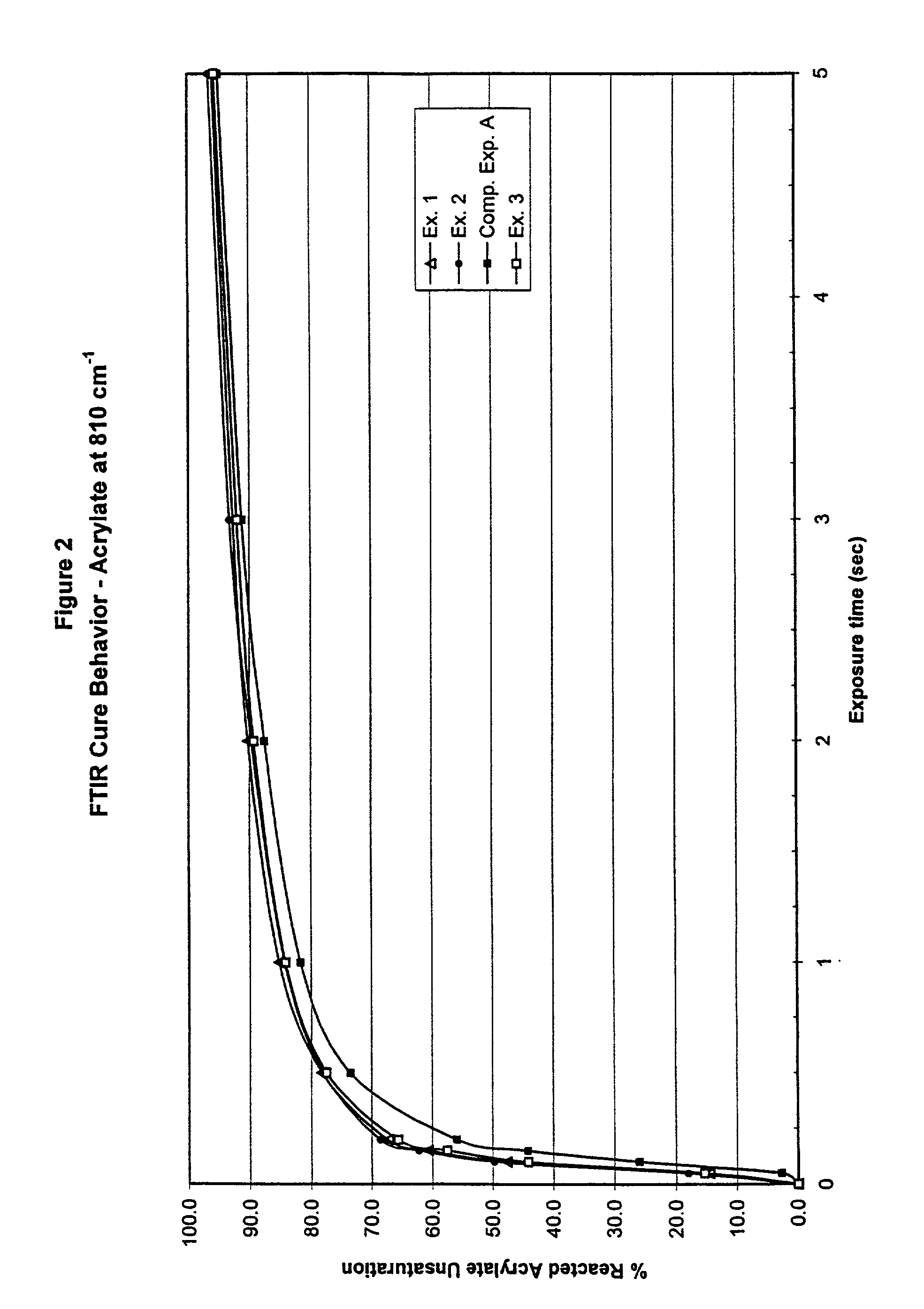
The present invention relates to a coated optical fiber comprising a glass optical fiber with a single protective coating or a combination of an inner and an outer primary coating applied thereon and optionally with a colored coating subsequently applied thereon wherein the inner primary coating or at least a portion of the single coating is prepared from a radiation curable composition which when cured as a capillary film with a 100W medium pressure mercury lamp has a percentage reacted acrylate unsaturation of at least about 54% after exposure to a dose of about 4.4 mJ / cm2 or wherein the outer primary coating is prepared from a radiation curable composition which when cured as a capillary film with a 100 W medium pressure mercury lamp has a percentage reacted acrylate unsaturation of at least about 56% after exposure to a dose of about 4.4 mJ / cm2. The invention further relates to a radiation curable composition having a high cure speed.

Description

CROSS REFERENCE TO RELATED APPLICATIONS[0001]This application claims priority from U.S. patent application Ser. No. 09 / 475,024, filed Dec. 30, 1999; from U.S. patent application Ser. No. 09 / 544,209, filed Apr. 7, 2000; and from international application PCT / NL01 / 00278, filed Apr. 5, 2001. All three applications are hereby incorporated in their entirety by reference.FIELD OF THE INVENTION[0002]The present invention relates to a coated optical fiber comprising a cured coating prepared from a radiation curable composition having improved cure speed without deteriorating the yellowing performance of the cured coating. In particular, the radiation-curable composition of the present invention is a liquid curable composition that can be formulated for use in a wide variety of applications including, for example, coatings and / or binders. In particular, these curable compositions offer relatively fast cure speeds which offer advantages in many applications such as in the production of fiber ...

Claims


Application Information

Patent Timeline
IPC IPC(8): C08F2/50C03C25/10C08F290/06C08G18/48C08G18/67C08G18/75C09D175/16
CPCC03C25/106C03C25/1065C08F290/067C08G18/4854C08G18/672C08G18/75C09D175/16C08G18/48C08G18/40Y10T428/2947Y10T428/2938
Inventor BISHOP, TIMOTHY E.SNOWWHITE, PAUL E.NORLIN, TYSONSCHOUTEN, JAMES J.SOUTHWELL, JOHNTOUSSAINT, ANTHONY
Owner COVESTRO NETHERLANDS BV
Learn More