Eureka AIR delivers breakthrough ideas for toughest innovation challenges, trusted by R&D personnel around the world.

Magnetic head actuator including piezoelectric elements fixed to the arms of a fired glass-ceramic substrate

a technology of piezoelectric elements and actuators, which is applied in the direction of maintaining head carrier alignment, generators/motors, instruments, etc., can solve the problems of particle separation, easy cracking or cracking of the compact of fired glass-ceramic, etc., and achieves sufficient mechanical strength, prevent particle separation, and minimal shrinkage

Inactive Publication Date: 2007-10-02
TDK CORPARATION
View PDF12 Cites 12 Cited by
  • Summary
  • Abstract
  • Description
  • Claims
  • Application Information

AI Technical Summary

Benefits of technology

[0009]Accordingly, an advantage of the present invention is that it provides a magnetic head actuator that can prevent the separation of particles and that has sufficient mechanical strength. Its manufacturing method is also disclosed.
[0010]The present invention features glass-ceramic materials, which can be sintered at low temperature with minimal shrinkage and can be micromachined in the green sheet state. The term glass-ceramic materials as used herein refers to mixtures of glass and ceramics.
[0011]The present invention provides a magnetic head actuator comprising a head-holding substrate having a pair of movable arms for holding a magnetic head, and a pair of piezoelectric elements fixed along the pair of movable arms to move the pair of movable arms slightly in response to an applied voltage, wherein the head-holding substrate comprises a fired glass-ceramic compact and all surfaces of the substrate have been fired.
[0012]The fired glass-ceramic compact preferably contains at least one of SiO2, B2O3, and Al2O3. Such a fired glass-ceramic compact may have a mechanical strength of 200 MPa or more. Examples of such fired glass-ceramic compacts include a compact containing a glass component comprising PbO, B2O3, SiO2, CaO, and a ceramic component comprising Al2O3; a compact containing a glass component comprising MgO, Al2O3, SiO2, B2O3, and a ceramic component comprising SiO2; a compact containing a glass component comprising B2O3, SiO2, and and a ceramic component comprising Al2O3; CaO, Al2O3, and SiO2; and a compact containing a glass component comprising Li2O, SiO2, MgO, Al2O3, and a ceramic component comprising SiO2, and Al2O3. A head-holding substrate made of such a fired glass-ceramic compact is not easily chipped or cracked and can prevent the separation of particles even in long-term operation.
[0013]Preferably, the piezoelectric elements are formed on the head-holding substrate by printing and are fired at a lower temperature than the sintering temperature of the fired glass-ceramic compact. The piezoelectric elements can be formed by printing in narrow areas on the head-holding substrate. In addition, low-temperature firing can prevent the separation of particles from the piezoelectric elements and a decrease in the mechanical strength of the fired glass-ceramic compact. These piezoelectric elements are preferably made of a piezoelectric material having a lower sintering temperature than the fired glass-ceramic compact, for example, PZT.
[0014]The present invention also provides a method for manufacturing a magnetic head actuator, comprising: preparing a glass-ceramic green sheet; processing the glass-ceramic green sheet into a desired shape; firing the glass-ceramic green sheet by non-shrinkage firing to provide a fired glass-ceramic sheet for head-holding substrates, all surfaces of the fired glass-ceramic sheet being fired; forming a pair of piezoelectric elements on each head-holding substrate by printing with a piezoelectric material having a lower sintering temperature than that of the fired glass-ceramic sheet; and firing the pair of piezoelectric elements at a lower temperature than the sintering temperature of the fired glass-ceramic sheet.

Problems solved by technology

A head-holding substrate made of such a fired glass-ceramic compact is not easily chipped or cracked and can prevent the separation of particles even in long-term operation.

Method used


Image

  • Magnetic head actuator including piezoelectric elements fixed to the arms of a fired glass-ceramic substrate
  • Magnetic head actuator including piezoelectric elements fixed to the arms of a fired glass-ceramic substrate
  • Magnetic head actuator including piezoelectric elements fixed to the arms of a fired glass-ceramic substrate

Examples


Embodiment Construction

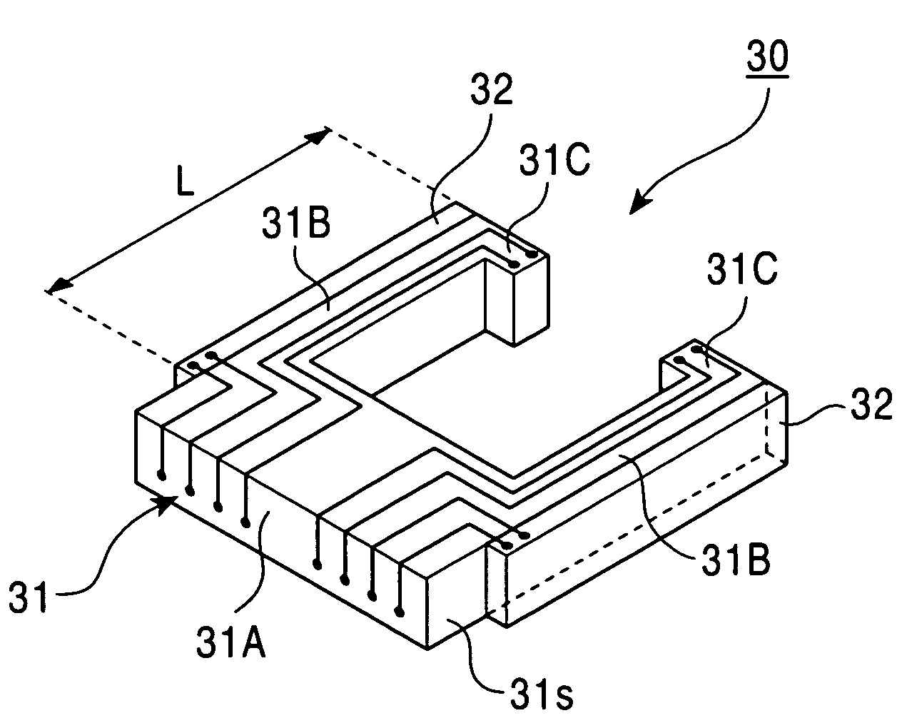
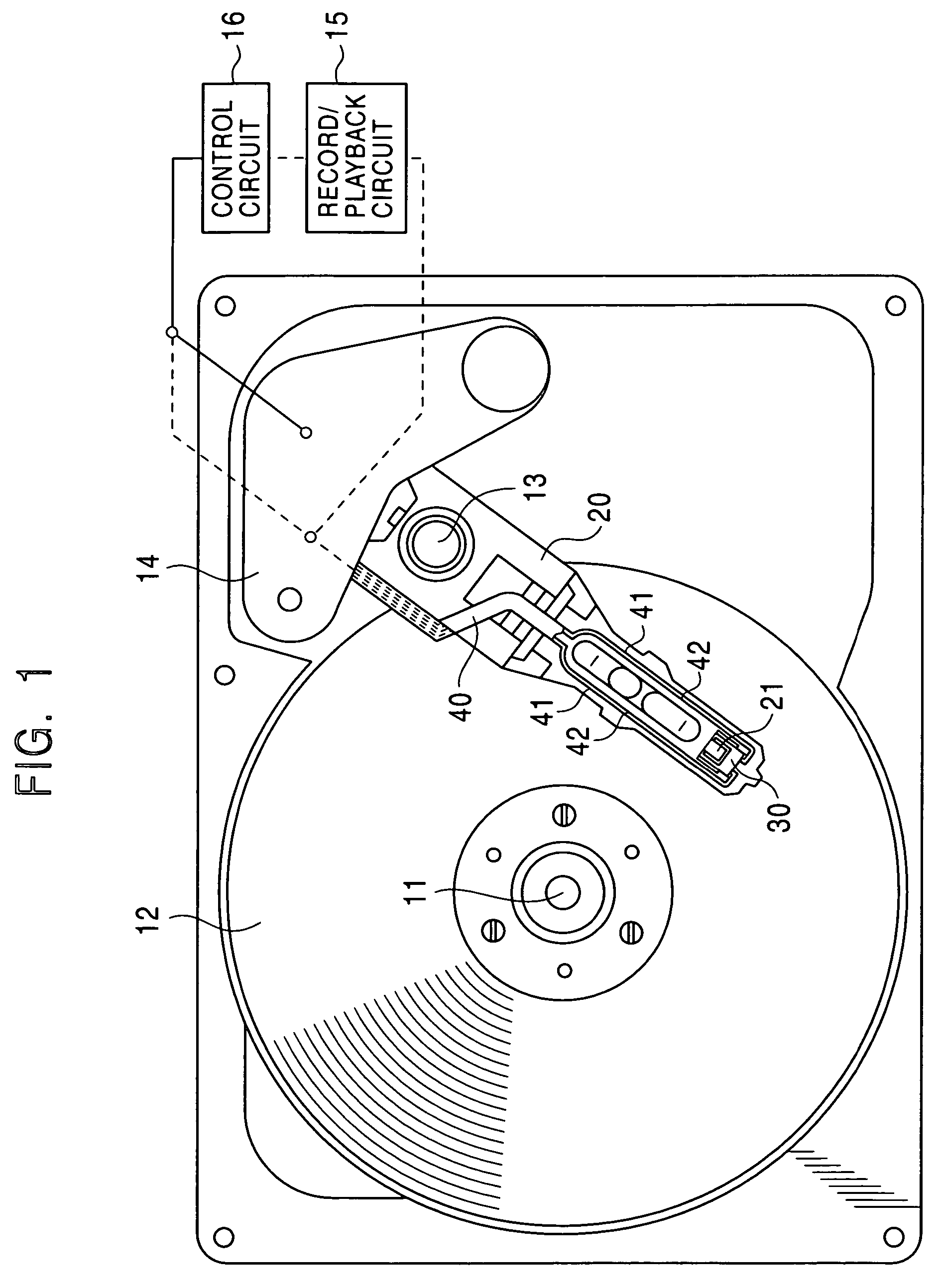
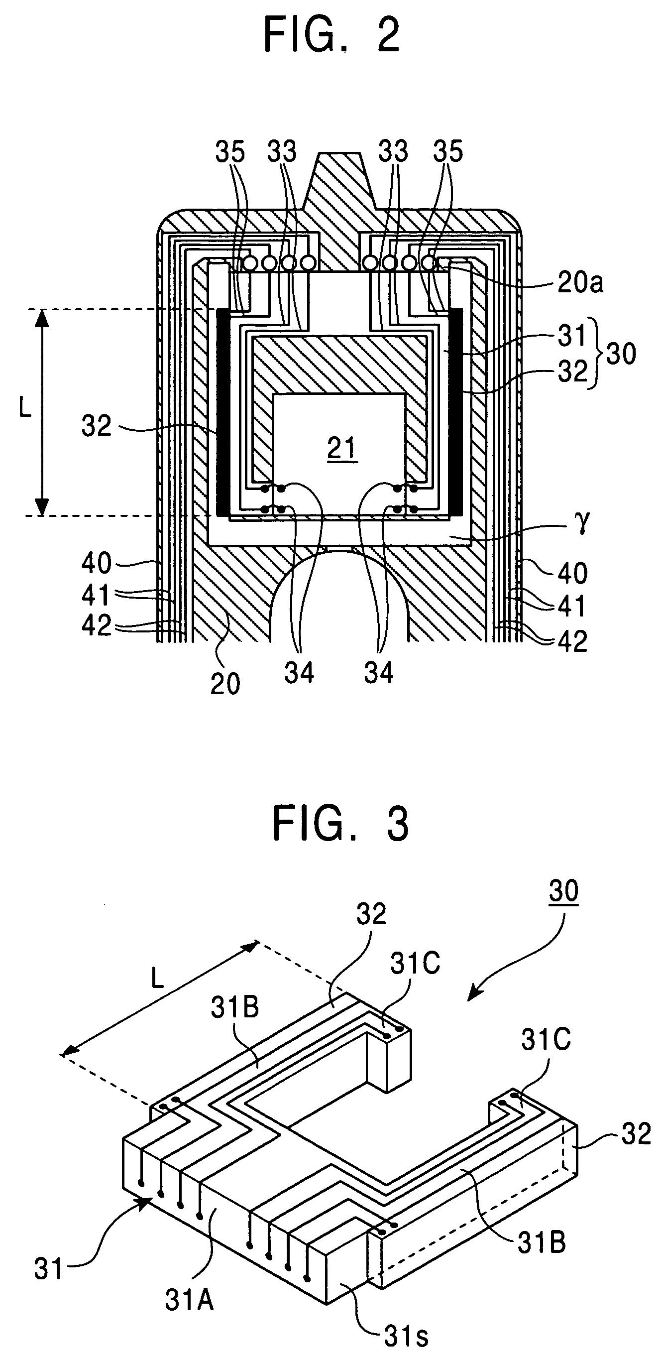
[0027]FIG. 1 shows the overall structure of a hard disc drive including a magnetic head actuator 30 according to the present invention. A hard disc 12 (a magnetic disc) rotates around a rotating shaft 11. A coarse adjustment shaft 13 beside the hard disc 12 supports the base of a swing arm 20 (a load beam or a gimbal blade), which is pivotable around the coarse adjustment shaft 13. Referring then to FIG. 2, a space γ defines a tongue portion 20a at the leading end of the swing arm 20. The tongue portion 20a holds a magnetic head 21 (a slider or a flexure). The swing arm 20 is elastic so as to support the magnetic head 21 flexibly at the tongue portion 20a. Referring back to FIG. 1, when an actuator 14 pivots the swing arm 20 around the coarse adjustment shaft 13, the magnetic head 21 reciprocates substantially along the radius of the hard disc 12.

[0028]Additionally, the tongue portion 20a holds the magnetic head actuator 30 for fine adjustment to the position of the magnetic head 21...


PUM

PropertyMeasurementUnit
mechanical strengthaaaaaaaaaa
temperaturesaaaaaaaaaa
thicknessaaaaaaaaaa

Abstract

A magnetic head actuator includes a head-holding substrate having a pair of movable arms for clamping a magnetic head, and piezoelectric elements fixed along the pair of movable arms to move the pair of movable arms in response to an applied voltage. The head-holding substrate comprises a fired glass-ceramic compact containing at least one of SiO2, B2O3, and Al2O3. The piezoelectric elements are formed on the head-holding substrate with a piezoelectric material by printing and low-temperature firing.

Description

[0001]This application claims the benefit of Japanese Patent Application No.: 2003-030258, filed on Feb. 7, 2003, which is incorporated herein by reference.BACKGROUND OF THE INVENTION[0002]1. Field of the Invention[0003]The present invention relates to magnetic head actuators for fine adjustment to the position of a magnetic head, and manufacturing methods for the same.[0004]2. Description of the Related Art[0005]In the development of hard disc drives, tracks have been made narrower to achieve higher storage capacity and higher recording density. Such narrower tracks make it difficult for known servo control techniques with a voice coil motor alone to position a magnetic head accurately over the tracks. In recent years, a wide variety of hard disc drives have been developed that include a magnetic head (slider) equipped with an actuator to assist the voice coil motor to position the magnetic head more precisely.[0006]Such magnetic head actuators include, for example, a head-holding ...

Claims


Application Information

Patent Timeline
Patent Type & Authority Patents(United States)
IPC IPC(8): G11B5/54G11B21/10G11B5/55G11B5/596G11B21/21H01L41/09H01L41/187H01L41/22H01L41/314H02N2/00
CPCG11B5/5552
Inventor YAMAMOTO, YUTAKAMURAKAMI, JUN-ICHISAWAIRI, HIROYA
Owner TDK CORPARATION
Why Eureka
Eureka Blog
Learn More