Lathe for machining optical workpieces

a technology of optical workpieces and lathes, applied in the direction of lenses, manufacturing tools, other manufacturing equipment/tools, etc., can solve the problems of high mechanical, electrical and control engineering outlay required to generate synchronous mass compensation movements, and achieve the effect of preventing the transmission of disruptive vibrations generated by the fast tool to the machine bed, simple and cost-effectiv

Inactive Publication Date: 2007-10-09
SATISLOH GMBH
View PDF18 Cites 14 Cited by
  • Summary
  • Abstract
  • Description
  • Claims
  • Application Information

AI Technical Summary

Benefits of technology

[0004]The object of the invention is to provide a lathe, in which the transmission of disruptive vibrations generated by the fast tool to the machine bed is prevented in a manner that is both simple and cost-effective.
[0006]So according to the basic concept of the invention, a heavy and rigid machine frame which has good damping properties and is made of polymer concrete is provided, said machine frame having a machine upper part made of polymer concrete which is molded on in one piece and in which machine elements, in particular the fast tool arrangement and the workpiece spindle arrangement, which are to be fitted on the machine bed, can be easily mounted and calibrated.
[0008]The one-piece manufacture of the polymer concrete machine frame opens up the advantageous possibility of forming all the functional surfaces, functional spaces and other cutouts to their exact dimensions at the time of manufacture. For example, the functional surfaces may include the mounting surfaces for the fast tool arrangement, the workpiece spindle arrangement with transverse slide arrangement and possibly an additional cutter spindle arrangement, and also the support surfaces for a control panel and depositing surfaces, while the functional spaces may for example include a working space, a cabinet space for pneumatic elements of the machine and a cabinet space for electrical / electronic elements of the machine.
[0009]Preferably, the lathe is designed in such a way that the center of gravity of the lathe lies approximately in the movement plane of the fast tool arrangement, as a result of which it is not possible for there to be any tilting moments about the center of gravity caused by the fast tool arrangement, which ensures a trouble-free machining operation.

Problems solved by technology

The disadvantage of the known type of mass compensation lies in the high mechanical, electrical and control engineering outlay required to generate synchronous mass compensation movements.

Method used


Image

  • Lathe for machining optical workpieces
  • Lathe for machining optical workpieces
  • Lathe for machining optical workpieces

Examples


Embodiment Construction

[0018]The one-piece machine frame 10 which is shown in the drawings is cast from a polymer concrete suitable for machine construction. Polymer concrete is a composite material consisting of a mineral filler blend and a binder based on reaction resin, and is also referred to as cast mineral composite on account of its composition. The reaction resin used is usually an epoxy resin, since epoxy resins are best able to satisfy the main requirements of the cast mineral composite, namely a high modulus of elasticity, good damping behavior, low internal stresses, minimal shrinkage for high dimensional accuracy and a low thermal expansion coefficient.

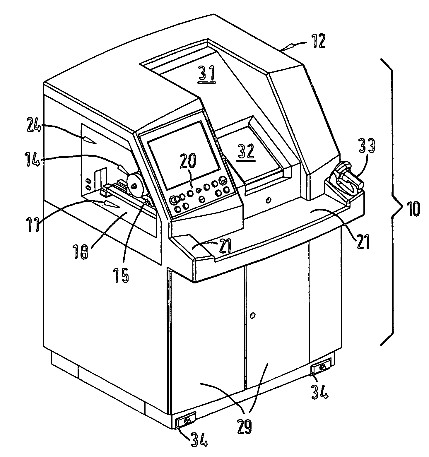
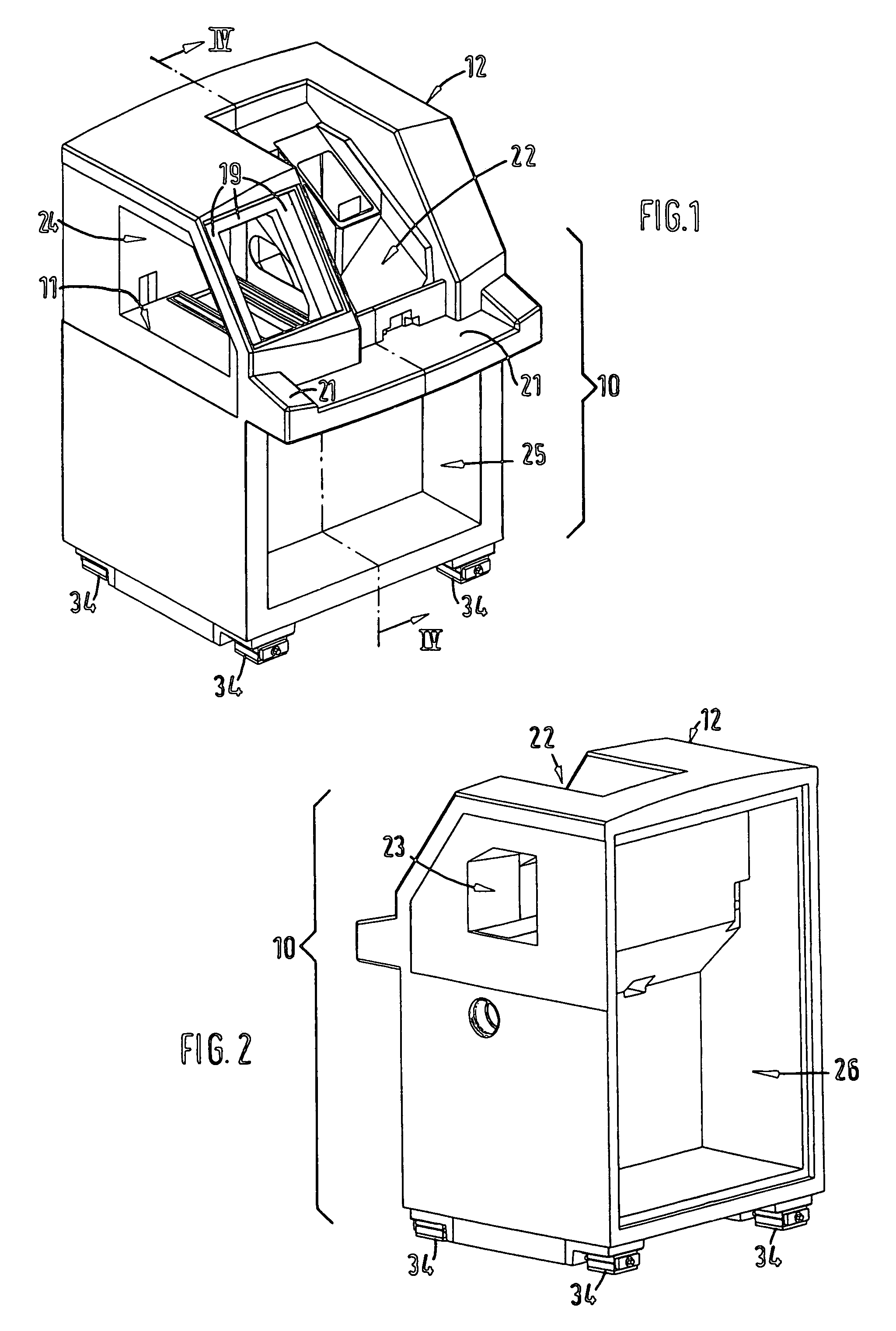
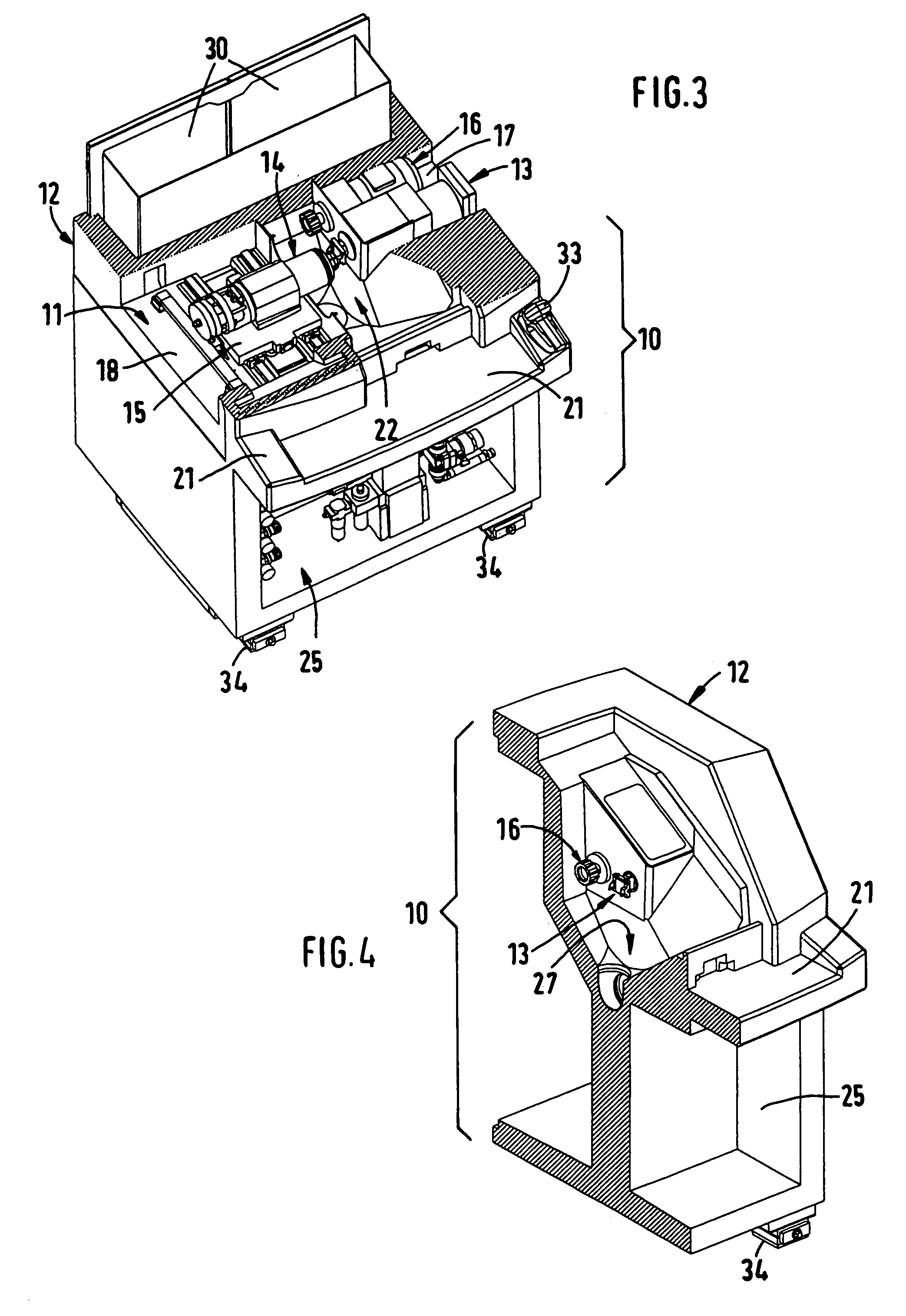
[0019]The machine frame 10 comprises a machine bed 11 and a machine upper part 12 which is cast in one piece therewith. As can best be seen from FIG. 3, the fast tool arrangement 13 and the workpiece spindle arrangement 14 are arranged on the machine bed 11 and fixed thereto by screwing, in the case of the workpiece spindle arrangement 14 via a...


PUM

PropertyMeasurementUnit
stroke lengthaaaaaaaaaa
massaaaaaaaaaa
massaaaaaaaaaa

Abstract

A lathe for machining optical workpieces, in particular spectacle lenses, comprises a fast tool arrangement and a workpiece spindle arrangement. A machine frame is cast monolithically from polymer concrete and on and in which all the functional surfaces, functional spaces and other cutouts are formed to their exact dimensions during the casting process. The machine frame upper part cast in one piece simultaneously covers the fast tool arrangement and the workpiece spindle arrangement and thus the machine bed in the manner of a covering hood. The machine frame is of compact dimensions, has a very rigid oscillation-damping machine bed and, in comparison with the rapidly moving elements of the fast tool arrangement, has a very large mass with a high center of gravity, which prevents the transmission of disruptive oscillations from the fast tool movement to the machine bed and thus to the workpiece spindle arrangement. The lathe can be manufactured in a cost-effective manner and allows the production of any spectacle lens optical surfaces with extremely high dimensional accuracy and surface quality. The achievable optical surface quality allows direct polishing by means of flexible or adaptable polishing tools, as a result of which considerable savings are made in the subsequent process. If suitably equipped with a cutter spindle arrangement, edge machining operations on the spectacle lenses can be carried out.

Description

BACKGROUND OF THE INVENTION[0001]The invention relates to a lathe for machining optical workpieces, in particular spectacle lenses.[0002]In the highly precise turning-machining of non-rotationally symmetrical spectacle lenses, use is made of so-called fast tools which are designed as turning tool mounts which can be moved in a highly dynamic manner and comprise a dedicated drive for guiding the turning tools in a linear-reciprocal or rotational movement. During the machining of such spectacle lenses, stroke movements of the turning tool of up to approx. 30 mm stroke length and extremely high accelerations of up to approx. 20 g take place. On account of these high accelerations in alternating directions of movement, oscillations are generated which are transmitted as vibrations to the machine frame. These vibrations are highly undesirable since they give rise to form errors on the machined optical workpiece surfaces.DESCRIPTION OF THE PRIOR ART[0003]It has already been proposed to co...

Claims


Application Information

Patent Timeline
Patent Type & Authority Patents(United States)
IPC IPC(8): B23B27/00
CPCB23Q1/015B23Q11/0035B24B13/046B23Q1/0045Y10T29/50Y10T409/30392Y10T82/2508Y10T29/5114
Inventor SCHAEFER, HOLGER
Owner SATISLOH GMBH
Why Eureka
Try Eureka