Method, code, and system for assaying joint deformity

a joint deformity and code technology, applied in the field of joint deformity assaying methods, codes and systems, can solve the problems of various limitations in the ability of methods to pinpoint and accurately quantitate joints

Active Publication Date: 2007-10-09
COMPUMED
View PDF25 Cites 23 Cited by
  • Summary
  • Abstract
  • Description
  • Claims
  • Application Information

AI Technical Summary

Benefits of technology

[0015]In another embodiment (Embodiment 3) for use in assaying or monitoring bone erosion in a patient joint, the selecting step may include (i) matching the coordinates of a minimum width coordinate in the middle region of the phalange and one or more apices on at least one side of the selected phalange adjacent the joint with corresponding coordinates in a partial or complete normal-finger template, to identify a joint region of a normal-finger phalange template that matches the subject finger joint region, and (ii) superimposing the contour of the template phalange joint region on the image of the patient-finger phalange joint region, where the template contour represents a reference joint contour adjacent the joint region of the selected phalange. The analyzing step includes comparing the template line contour in the joint region with the actual patient contour in the same region, to determine the extent to which the actual patient contour deviates from the normal-phalange contour.
[0016]In still another embodiment (Embodiment 4) for use in assaying or monitoring bone erosion in a patient joint, the selecting step may include (i) matching the coordinates of a minimum width coordinate in the middle region of the phalange and one or more apices on at least one side of the selected phalange adjacent the joint with corresponding coordinates in a previous patient x-ray image of the finger phalange, and (ii) superimposing the contour of the previous x-ray image phalange on the image of the patient-finger phalange, where the previous-patient contour represents a reference contour of the selected phalange. The analyzing step includes comparing the previous-image contour in the joint region with the actual patient contour in the same region, to determine the extent to which the actual patient contour deviates from the previous-image contour.
[0017]In another aspect, the invention includes machine-readable storage medium embodying computer-readable code which is operable, when used to control the operation of an electronic computer, to carry out the steps in the above method for assaying or monitoring the extent of joint or bone deformity in a joint-degenerative or joint-damaging disease.
[0018]Also disclosed is an automated system for use in assaying or monitoring the extent of joint or bone deformity in a joint-degenerative or joint-damaging disease, such as arthritis or osteoporosis. The system includes an electronic computer, and machine-readable storage medium embodying computer-readable code which is operable, when used to control the operation of the computer, to carry out the steps in the above method, where the selecting step in the method includes matching contour coordinates for a selected patient phalange with one or more of a plurality of normal-phalange templates from a library of templates. The system also includes a library of normal-phalange templates that is accessible by the code for use in carrying out the selecting step in the method. The library forms yet another aspect of the invention.

Problems solved by technology

These methods suffer various limitations relating to ability to pinpoint and accurately quantitate joint-degenerative conditions in an automated or substantially automated way.

Method used


Image

  • Method, code, and system for assaying joint deformity
  • Method, code, and system for assaying joint deformity
  • Method, code, and system for assaying joint deformity

Examples


embodiment 1

A. EMBODIMENT 1

Measuring JWS

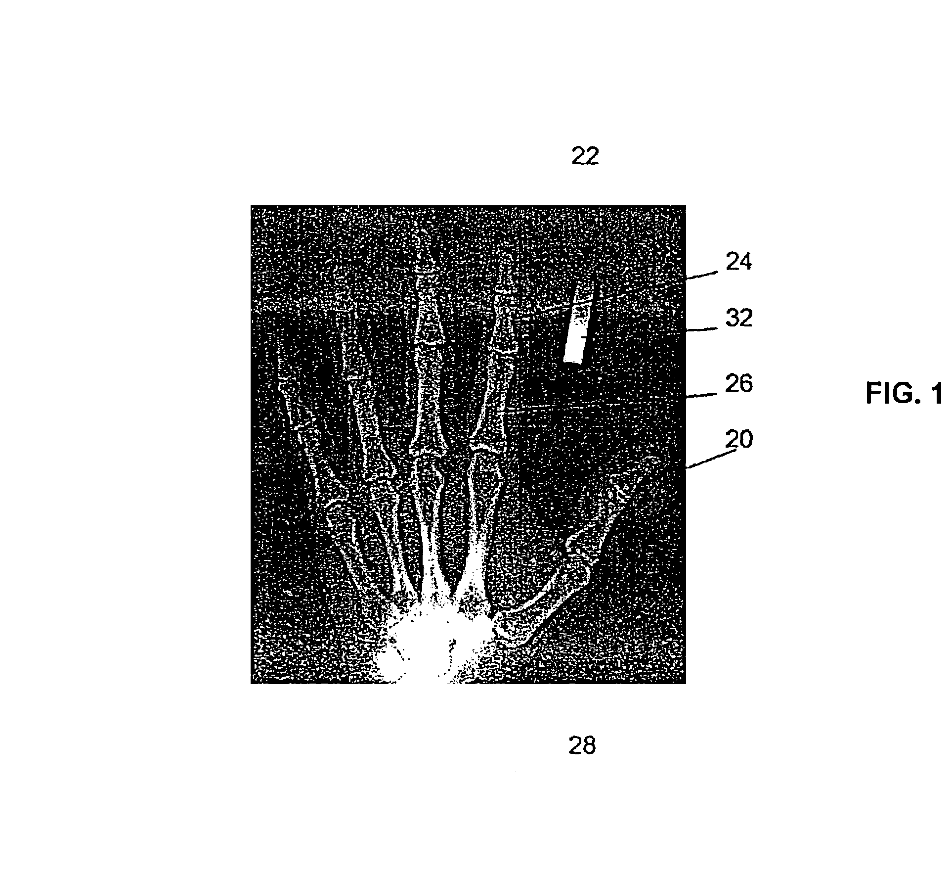
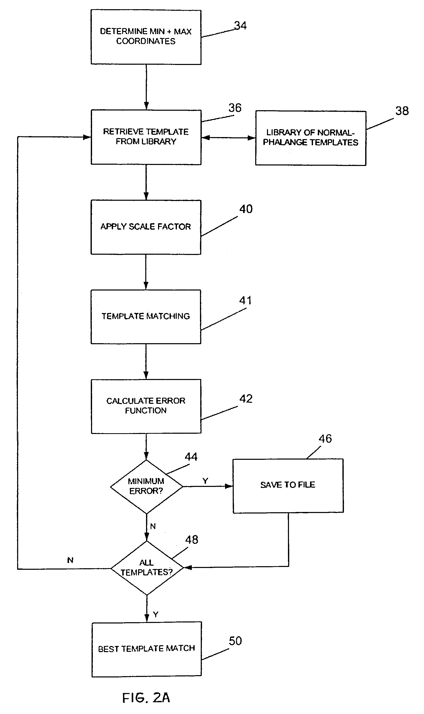
[0048]FIGS. 2A and 2B show a flow diagram of steps performed by the machine-readable storage medium embodying computer-readable code of the invention, in carrying out the method of Embodiment 1. As indicated by box 34 in the figure, the coordinates that are determined from the x-ray images are the coordinates at the left and right edges of the bone at its narrowest width (Min), and the apical coordinates corresponding to coordinates at the ends of a line through the widest portion of the phalange (Max) adjacent one or both joints of that phalange, for example, the greatest widths at the top and bottom joint regions of the middle flange.

[0049]The coordinates are determined by using the left and right bone edge contours to find the minimum bone width of the middle phalange. Starting from the first coordinate of the left bone edge contour, the program finds the corresponding coordinate that has the same Y coordinate from the right bone edge contour. The widt...

embodiment 2

B. EMBODIMENT 2

Measuring Joint Bone Erosion

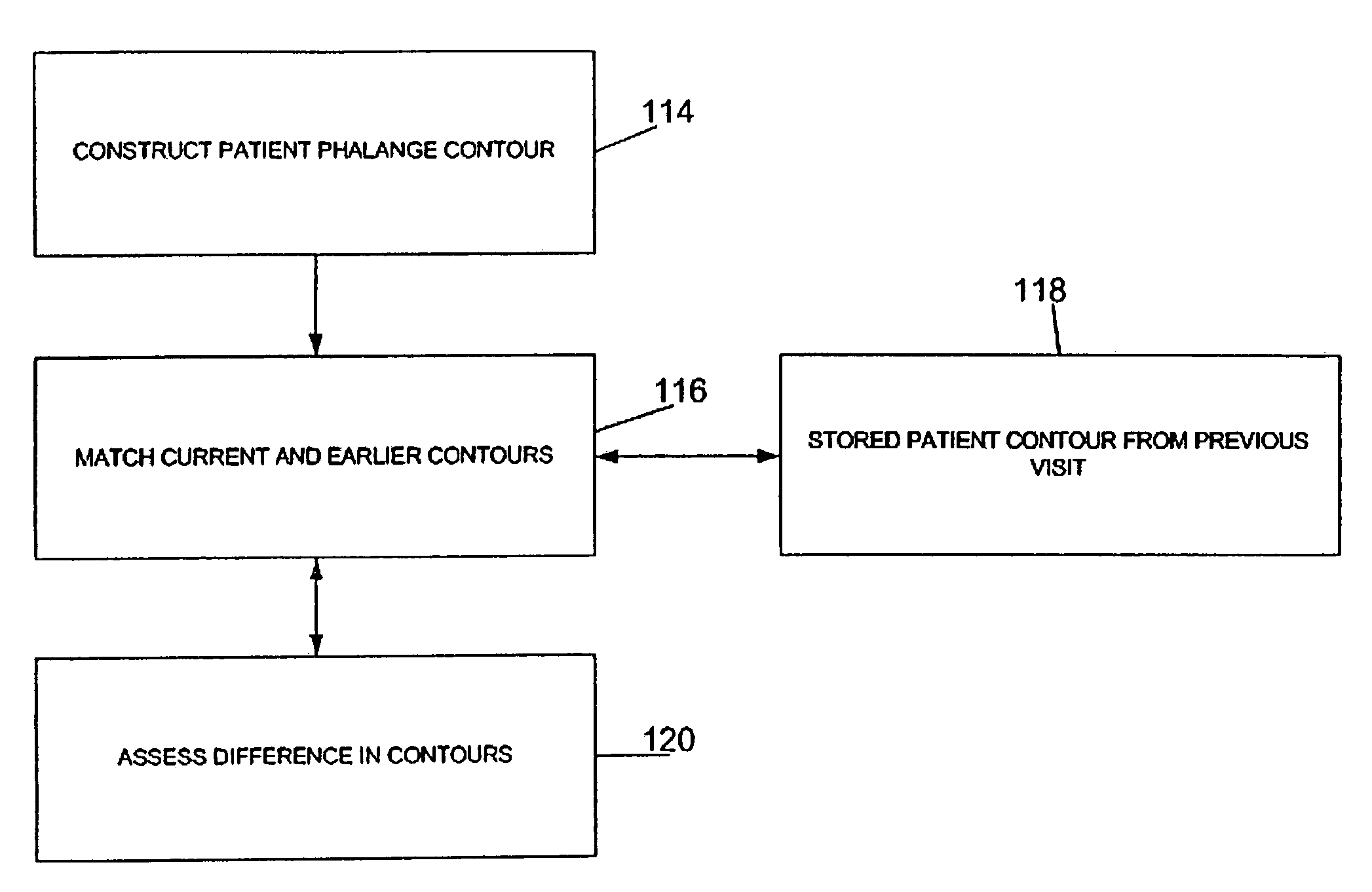
[0074]Erosion happens in early stages in RA patients and it rapidly gets worse in the first few years of the disease. When a patient is first seen, the physician's objective is to detect the existence and the severity of bone erosion. At this time the contours of the interested bones are obtained for the first time and saved as baseline results for future monitoring purpose. Embodiment 2 described in this section and Embodiment 3 described in the next sections are designed to assess the extent of bone loss in the joint region of a selected bone, e.g., phalange, using normal-bone contours to as reference contours. In follow-up visits, the patient's own earlier x-ray images may be used as the reference contours, for assessing the change in bone erosion over time. This approach is detailed below as Embodiment 4.

[0075]When the patient's bone contours are obtained for the first time, there are no preexisting contours to reference in the database...

embodiment 3

C. EMBODIMENT 3

Measuring Joint Bone Erosion

[0081]The method in this embodiment uses a portion of MP or PP templates to predict or estimate a normal contour (without erosion). Then, the current contour can be compared against the estimated contour to determine the existence and severity if the erosion.

[0082]From a MP or PP template, the algorithm defines two landmark points (described below in detailed steps) and applies a matching algorithm only on the contour points between them. By “copying over” the shape of the template's contour—the points between the two landmarks—for the area of interest (the area the erosion is supposed to occur), it is possible to partially overlay two contours and compare. The algorithm is shown in flow diagram in FIG. 7.

[0083]As a first step, indicated at box 92 in FIG. 7, the program finds the coordinates for an apical point P, as carried out in Embodiment 2, and the coordinates for the minimum width of the phalange (points N), as discussed below. These ...


PUM


Abstract

A method, machine-readable storage medium embodying computer-readable code and automated system for assaying or monitoring the extent of joint or bone deformity reported by a summarized score that may include joint space narrowing, bone erosion and periarticular osteoporosis in a joint-degenerative or joint-damaging disease in a subject are disclosed. From a digitized image of one of the subject's straight bone terminated with a joint such as fingers, coordinates of right and left bone contours of a selected middle or proximal phalange are determined, and these coordinates are in turn used to determine the coordinates of a minimum width in the middle region of the phalange and one or more apices in a region adjacent at least one side of a joint of the selected phalange. These latter coordinates are used in selecting a reference joint contour representing normal-bone contour for that phalange, or the contour of the patient phalange from an earlier x-ray image. Guided by the reference joint contour, a region of the selected joint of the patient is analyzed to assay or monitor the extent of joint or bone deformity in the subject.

Description

[0001]This application claims the benefit of U.S. Provisional application Ser. No. 60 / 397,943, filed Jul. 22, 2002, which is incorporated herein by reference in its entirety.FIELD OF THE INVENTION[0002]The present invention relates to an automated method and system for assaying or monitoring the extent or progression of joint or bone deformity in a joint-degenerative or joint-damaging disease, such as osteoarthritis or deformity joint disease such as rheumatoid arthritis.BACKGROUND OF THE INVENTION[0003]There are a variety of joint-degenerative and joint-damaging diseases, such as various forms of arthritis and osteoporosis, that have important health and quality-of-life consequence to patients. Since these diseases tend to be progressive, it is also important to be able to monitor change in joint or bone deformity, for example, in monitoring treatment methods.[0004]A variety of biochemical and physical analysis tools are available for monitoring bone and joint resorption and degene...

Claims


Application Information

Patent Timeline
Patent Type & Authority Patents(United States)
IPC IPC(8): G06K9/00A61B5/103A61B6/00
CPCA61B5/4509A61B5/4528G06K9/6203A61B6/505G06K2209/055G06V10/7515G06V2201/033
Inventor BI, XIAOLISHIM, JOON
Owner COMPUMED
Why Eureka
Try Eureka