Internal combustion engine provided with double system of fuel injection

a technology of fuel injection and combustion engine, which is applied in the direction of fuel injecting pump, machine/engine, electric control, etc., can solve the problem of fear of lean mixed fuel injection, and achieve the effect of improving air/fuel mixture performan

Active Publication Date: 2007-10-16
INTEL CORP +2
View PDF90 Cites 26 Cited by
  • Summary
  • Abstract
  • Description
  • Claims
  • Application Information

AI Technical Summary

Benefits of technology

[0012]An object of the present invention is therefore to substantially eliminate defects or drawbacks encountered in the prior art mentioned above and to provide a double system of fuel injection type internal combustion engine capable of always ensuring an optimum pressure and temperature of a fuel in a direct injection injector and improving air / fuel mixture performance at the time of fuel injection through the direct injection injector.

Problems solved by technology

However, in such a mechanical pressure control valve as mentioned above, in order to remove, in a short time, the fuel in the form of vapor generated in a fuel supply line, it was necessary to reduce the pressure in the delivery pipe through the fuel injection of the injector, which requires an unnecessary fuel injection for the pressure reduction.
Here, if the structure in which valve portion in such conventional fuel injection type internal combustion engine is driven by the electromagnetic drive is applied as it is to the direct fuel injection injector of the double system of the fuel injection, there may cause a problem at a time when the fuel injected from the port fuel injection injector is fully (100%) used, and on the other hand, the fuel injected from the direct injection injector is not (0%) used (that is, in a state that the direct injection injector is not operated).
At this time, although the pressure in the delivery pipe may be reduced by the operation of the relief valve, the fuel expands because of the heat increase and the fuel density becomes lower, and if such a low density fuel is injected from the direct injection injector, there is a fear of injection of lean mixed fuel.

Method used


Image

  • Internal combustion engine provided with double system of fuel injection
  • Internal combustion engine provided with double system of fuel injection
  • Internal combustion engine provided with double system of fuel injection

Examples


Embodiment Construction

[0040]One preferred embodiment according to the present invention will be described hereunder.

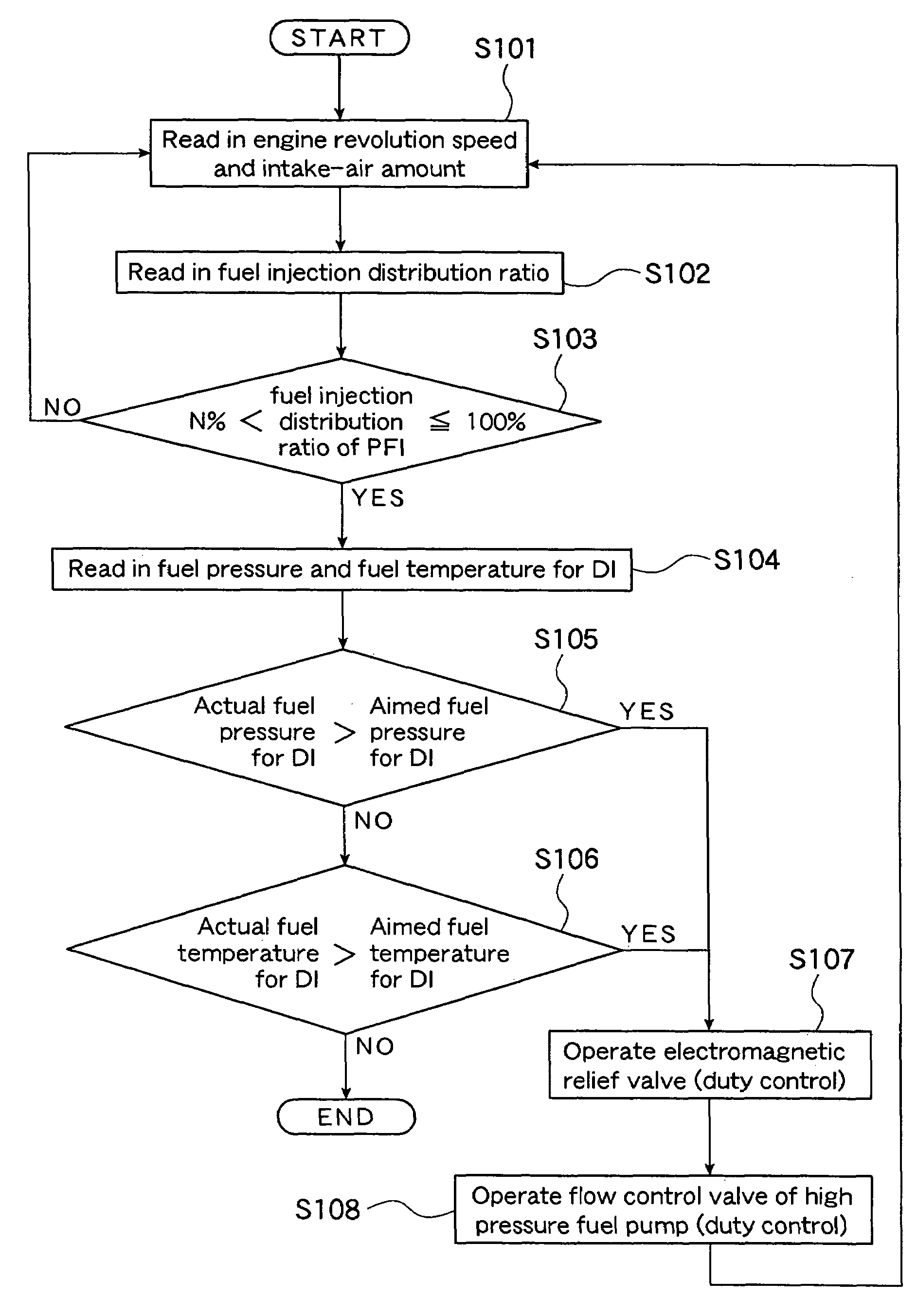
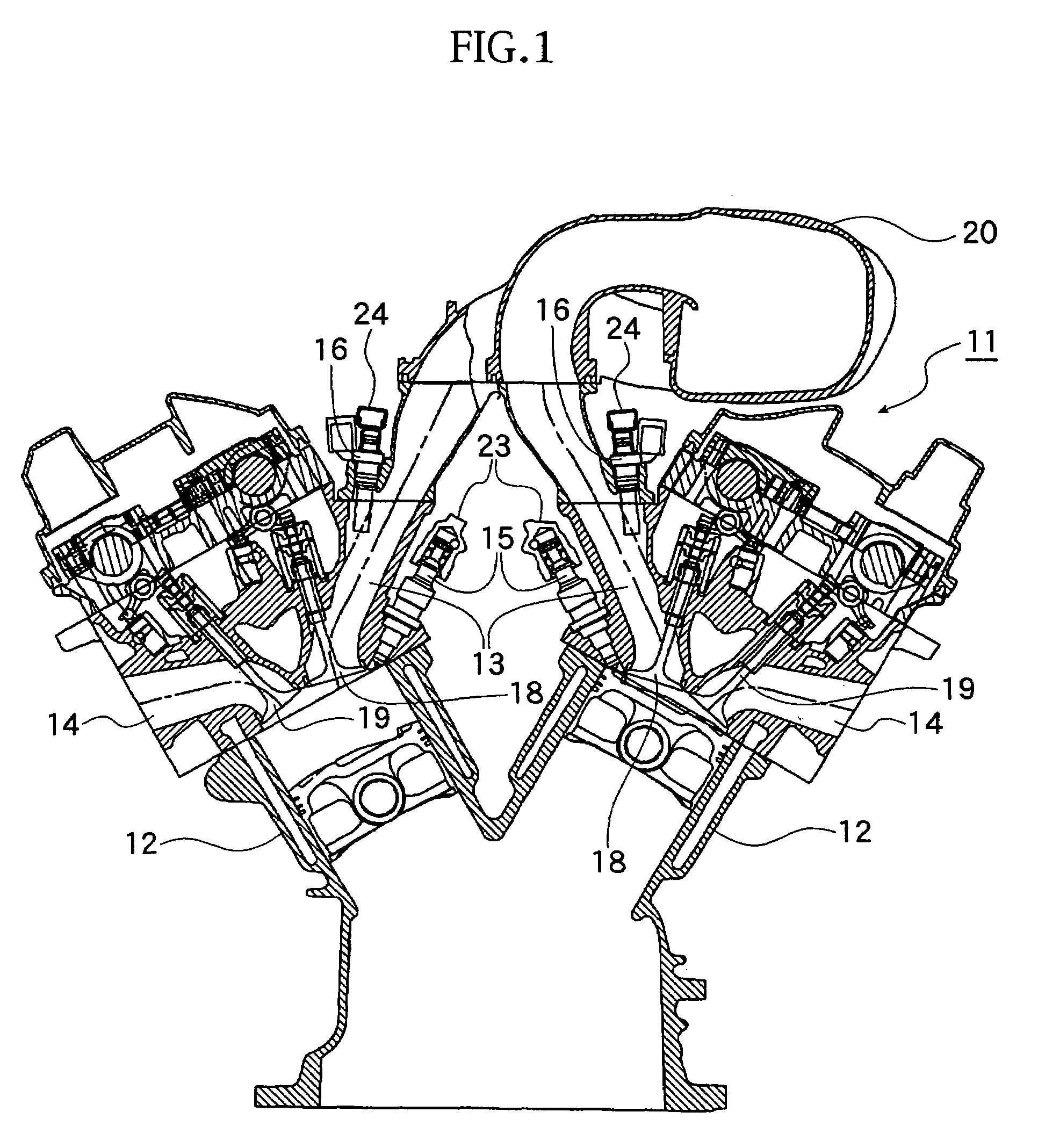
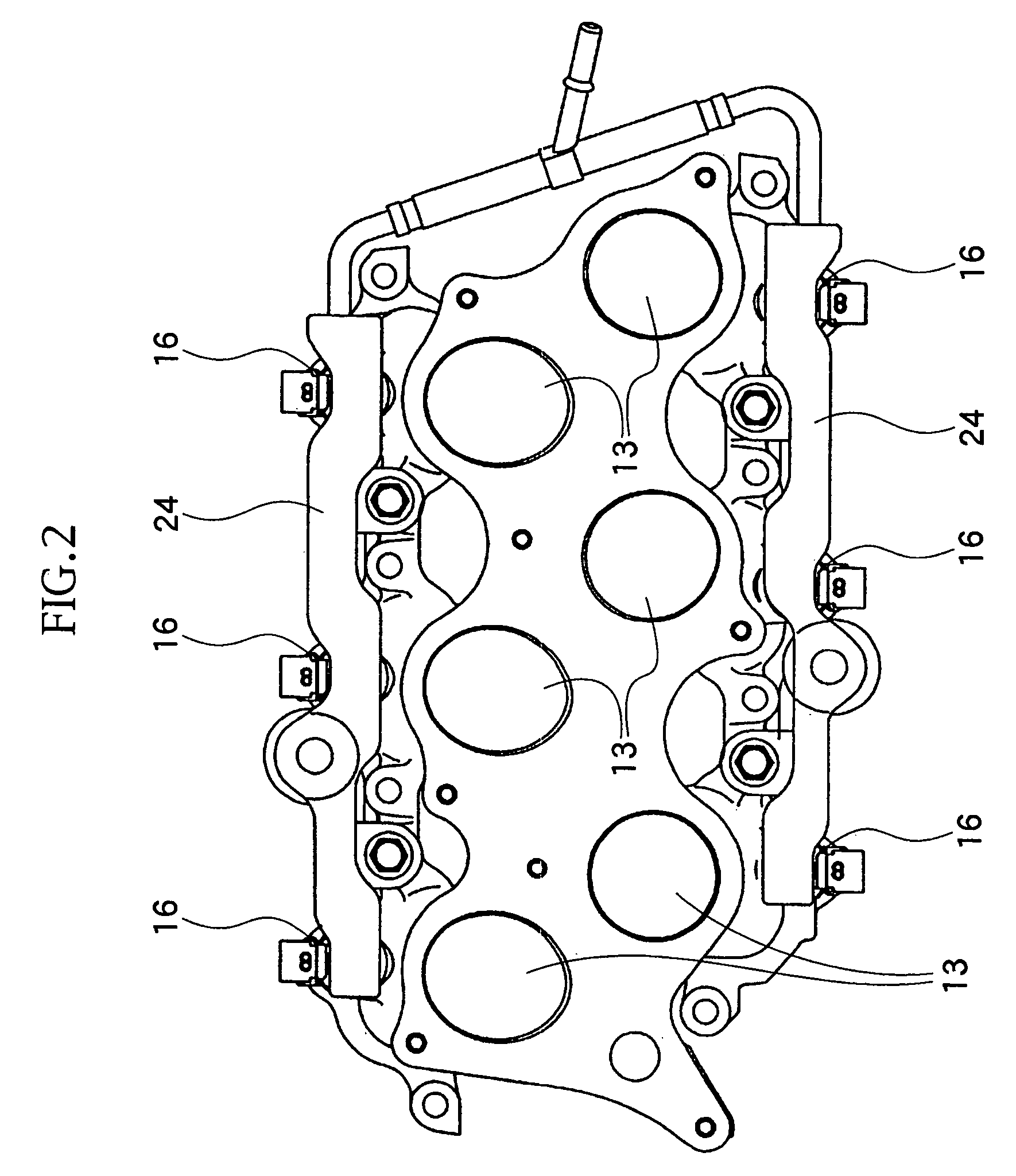
[0041]With reference to FIGS. 1 to 6, reference numeral 11 denotes a 6-cylinder engine as a double system of fuel injection type internal combustion engine (which may be called hereinlater merely “engine”) of the present invention, in which an intake port 13 and an exhaust port 14 are connected to each of the cylinders 12, which is in addition provided with a direct injection-type injector (DI injector) 15 and a port fuel injection-type injector (PFI injector) 16.

[0042]The fuel is directly injected into the cylinder, i.e., combustion chamber, 12 from the DI injector 15 and is then mixed with air in the cylinder 12, and in addition, the fuel is injected into the intake port 13 through the PFI injector 16 and is then mixed with air passing in the intake port 13. The thus mixed fuel is sucked in the cylinder 12 and burnt therein by an ignition of an ignition plug, not shown, at a predetermined...


PUM


Abstract

A double system of fuel injection type internal combustion engine includes: a direct injection injector and a port fuel injection injector; a control unit for changing a fuel injection distribution ratio of fuels injected from these injectors; a delivery pipe for the direct injection injector; a high pressure fuel pump; a fuel pressure sensor and a fuel temperature sensor for detecting a fuel pressure and a fuel temperature in the delivery pipe; and a fuel regulating unit for regulating the fuel pressure and fuel temperature in the delivery pipe. The control unit can control the fuel regulating unit so as to lower the exceeding value thereof when the fuel injection distribution ratio of the port fuel injection injector is higher than that of the direct injection injector and at least one of the fuel pressure value and fuel temperature value exceeds an aimed value.

Description

CROSS REFERENCE TO RELATED APPLICATION[0001]This application is based upon and claims the benefit of priority from prior Japanese Patent Application No. 2005-080697 filed on Mar. 18, 2005, the entire contents of which are incorporated herein by reference.BACKGROUND OF THE INVENTION[0002]1. Field of the Invention[0003]The present invention relates to an internal combustion engine provided with double system of fuel injection including a direct injection (DI) system and a port fuel injection (PFI) system.[0004]2. Related Art[0005]In a conventional art, there is known, in a fuel supply system for supplying a high pressure fuel to an injector through a delivery pipe from a high pressure fuel pump, a fuel supply device adapted to connect a mechanical pressure control valve to the delivery pipe. In such fuel supply device, when the fuel pressure in the delivery pipe exceeds over a predetermined pressure, the pressure control valve is opened to thereby discharge the fuel from the delivery ...

Claims


Application Information

Patent Timeline
Patent Type & Authority Patents(United States)
IPC IPC(8): F02D41/30F02M69/54
CPCF02D41/30F02D41/3094F02D41/3836F02M63/0225F02M63/028F02M63/029F02M63/023F02D2041/389F02D2041/2027F02M69/044F02M69/465
Inventor MIYAZAKI, KAZUMASAKAI, MITSUTOIWAMI, YUTAKANISHIGAKI, MASATOSHIMOJIKKOKU, YUKIO
Owner INTEL CORP
Why Eureka
Try Eureka