Scanning probe microscopy tips composed of nanoparticles and methods to form same

Inactive Publication Date: 2007-10-16
IBM CORP
View PDF42 Cites 37 Cited by
  • Summary
  • Abstract
  • Description
  • Claims
  • Application Information

AI Technical Summary

Benefits of technology

[0012]In view of the foregoing and other problems, disadvantages, and drawbacks of the conventional material compositions of the probe tips of scanning probe microscopes, the pr

Problems solved by technology

MFM sensors fabricated in this manner are limited in resolution by two main factors: 1) the film thickness of the magnetic coating layer increases the tip radius-of-curvature, thus decreasing resolution; and 2) the size of the magnetic domains in such a continuous thin-film also limits the resolution.
Both of these techniques are quite labor-intensive and are difficult to implement in

Method used


Image

  • Scanning probe microscopy tips composed of nanoparticles and methods to form same
  • Scanning probe microscopy tips composed of nanoparticles and methods to form same
  • Scanning probe microscopy tips composed of nanoparticles and methods to form same

Examples


Embodiment Construction

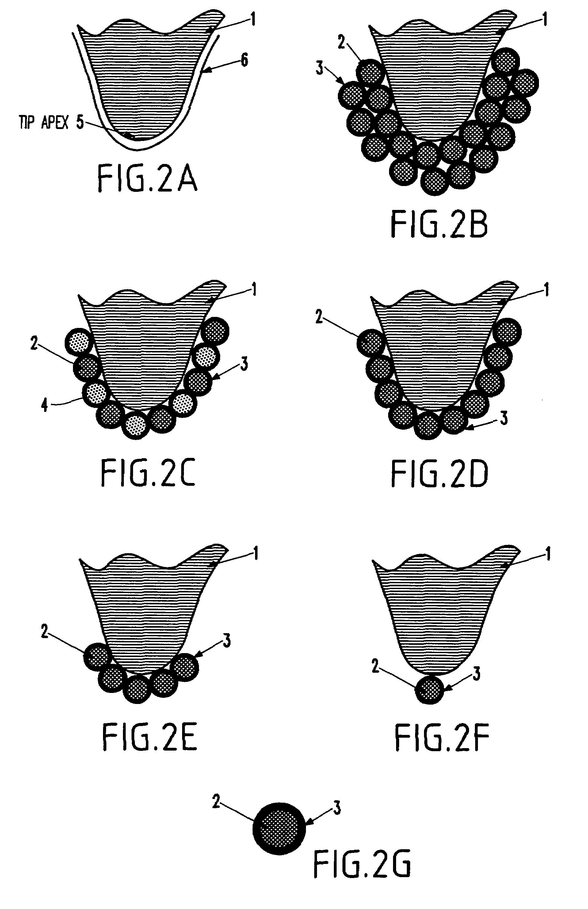
[0027]As mentioned above, there is a need for a scanning probe microscope with improved spatial resolution. In order to increase the spatial resolution, the invention forms the microscope probe tip using chemically synthesized nanoparticles. The advantage conferred by a tip coated with chemically synthesized nanoparticles is that the region on the tip that interacts with the substrate is limited to a few nanoparticles. For a tip coated with magnetic nanoparticles, this region is much smaller than the interaction-region on MFM tips fabricated by conventional processes. The smaller interaction-region leads to higher spatial resolution.

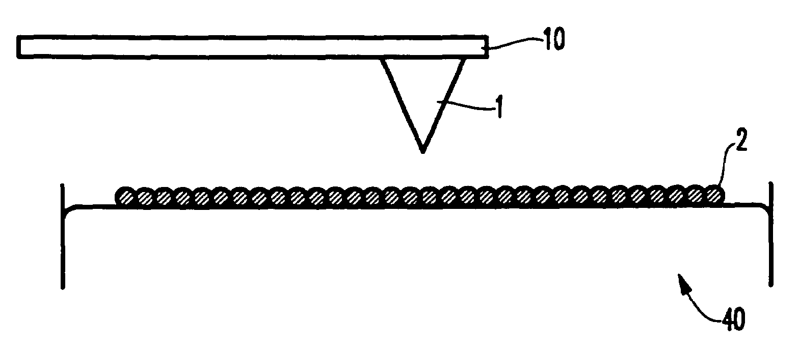
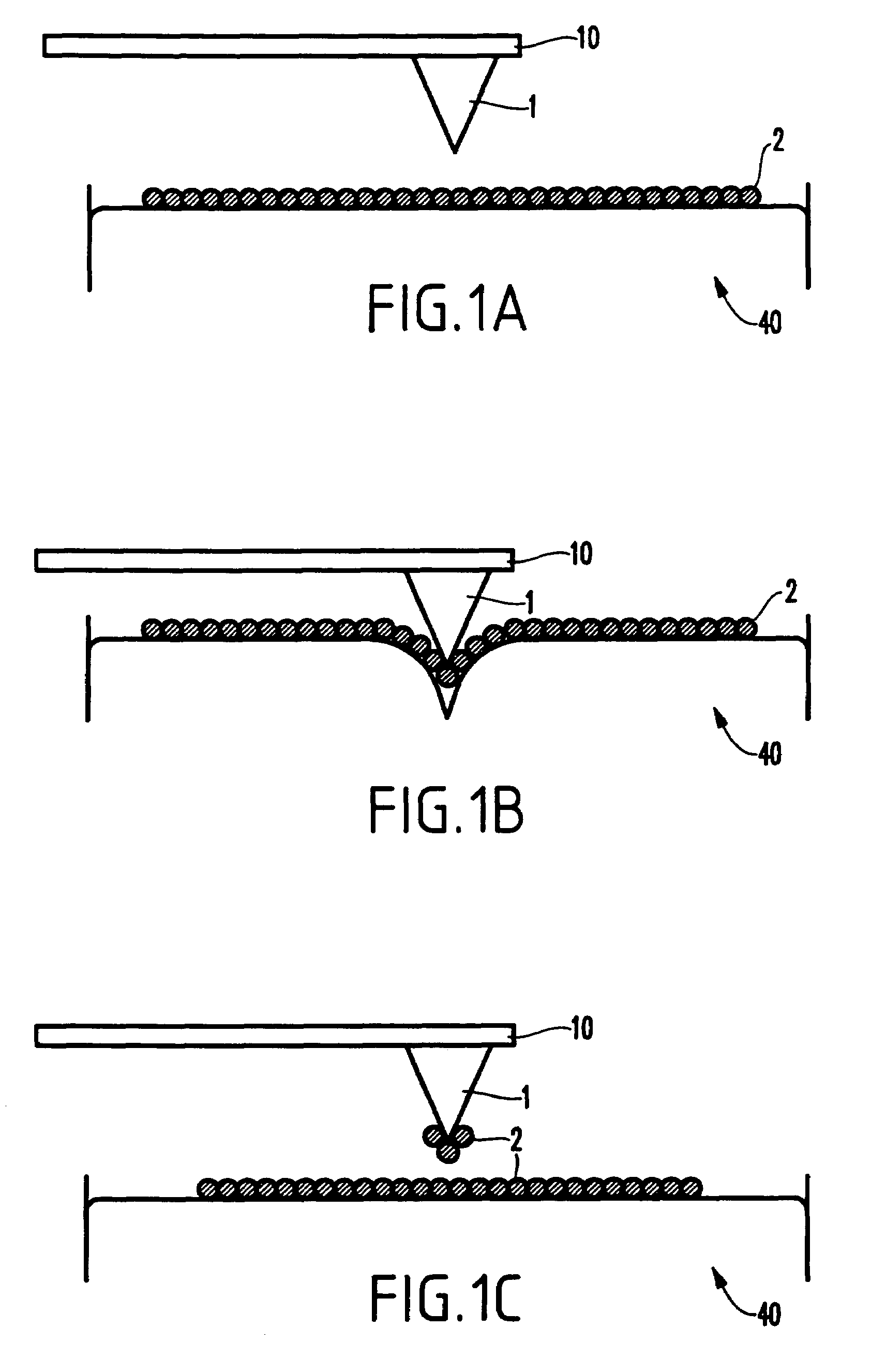
[0028]In a preferred embodiment of the present invention, the process of coating the tip is shown in sequence in FIGS. 1(a), 1(b), and 1(c). FIG. 1 is not drawn to scale; wherein nanoparticles have a typical diameter of 2 nm-20 nm; the tip apex has a typical diameter of 20 nm-50 nm; and the tip has a typical height of 10 μm-30 μm. A nonmagnetic silicon A...


PUM

PropertyMeasurementUnit
Fractionaaaaaaaaaa
Diameteraaaaaaaaaa
Diameteraaaaaaaaaa

Abstract

A structure and method for improving the spatial resolution of a scanning probe microscope (SPM) tip, which has been coated with a layer of chemically-synthesized nanoparticles. The nanoparticles are either single-species or heterogeneous, such that the single-species nanoparticles can be either ferromagnetic, paramagnetic, superparamagnetic, antiferromagnetic, ferrimagnetic, magneto-optic, ferroelectric, piezoelectric, superconducting, semiconducting, magnetically-doped semiconducting, insulating, fluorescent, or chemically catalytic. The layer of nanoparticles is at least two nanoparticles thick, or alternatively, is a single layer of nanoparticles thick, or alternatively, is a single layer of nanoparticles thick and covers only the tip apex portion of the tip, or alternatively, only a single nanoparticle is affixed to the tip apex. Alternatively, the layer of nanoparticles is transformed into an electrically-continuous magnetic film by annealing at a high temperature.

Description

BACKGROUND OF THE INVENTION[0001]1. Field of the Invention[0002]The present invention generally relates to scanning probe microscopy (SPM) and more particularly to a scanning probe microscope tip with improved spatial resolution using chemically-synthesized nanoparticles.[0003]2. Description of the Related Art[0004]In scanning probe microscopy, specimens are imaged by scanning a sharp probe tip in close proximity to the specimen surface. Data acquired from the probe tip is plotted as a function of the location of the probe tip in the plane of the specimen surface.[0005]Magnetic force microscopy is one of numerous scanning probe microscopy (SPM) techniques. Magnetic force microscopy is a probe to image magnetic fields in magnetic thin films. In the past, spatial resolution of magnetic details of approximately 10 nm has been achieved. Therefore, using a magnetic force microscope (MFM) is an effective tool to measure small magnetic fields arising from submicrometer scaled features.[000...

Claims


Application Information

Patent Timeline
IPC IPC(8): G01B7/34
CPCB82Y35/00G01Q70/16G01Q70/14B82Y15/00Y10T428/254Y10S977/924
Inventor BLACK, CHARLES T.COHEN, ADAM E.MURRAY, CHRISTOPHER B.SANDSTROM, ROBERT L.
Owner IBM CORP
Why Eureka
Try Eureka