Fluorescent-light image display method and apparatus therefor

a fluorescent light and image display technology, applied in the field of fluorescent light image display methods and apparatus therefor, can solve the problems of inability to recognize living tissue subjects under examination visually, weak strength of reflected light due to reference light that has been illuminated, and and achieves cost-effectiveness. , the effect of avoiding large fluctuation in the display gradation of brightness data of an image to be displayed

Inactive Publication Date: 2007-10-16
FUJIFILM CORP +1
View PDF19 Cites 24 Cited by
  • Summary
  • Abstract
  • Description
  • Claims
  • Application Information

AI Technical Summary

Benefits of technology

[0017]In view of this, it is a further object of the present invention to provide a fluorescent-light image display apparatus capable of displaying a diagnostic image having adequate brightness even when the strength of the reflected- light due to the reference light that has been illuminated becomes weak.
[0086]Still further, if a GaN type semiconductor laser is used as the stimulating-light source, a cost-effective small-sized light source can be provided, and also, if the wavelength band of the simulating light is in the 400-420 nm range, fluorescent light is efficiently emitted from a target area irradiated thereby.

Problems solved by technology

Accordingly, when the distance between the forward end of the insertion portion and the living-tissue subject under examination is toward the upper end of this range, the strength of the reflected-light due to the reference light that has been illuminated becomes weak, and as a result, the brightness image becomes dark overall and the living-tissue subject under examination is unable to be recognized visually.

Method used


Image

  • Fluorescent-light image display method and apparatus therefor
  • Fluorescent-light image display method and apparatus therefor
  • Fluorescent-light image display method and apparatus therefor

Examples


first embodiment

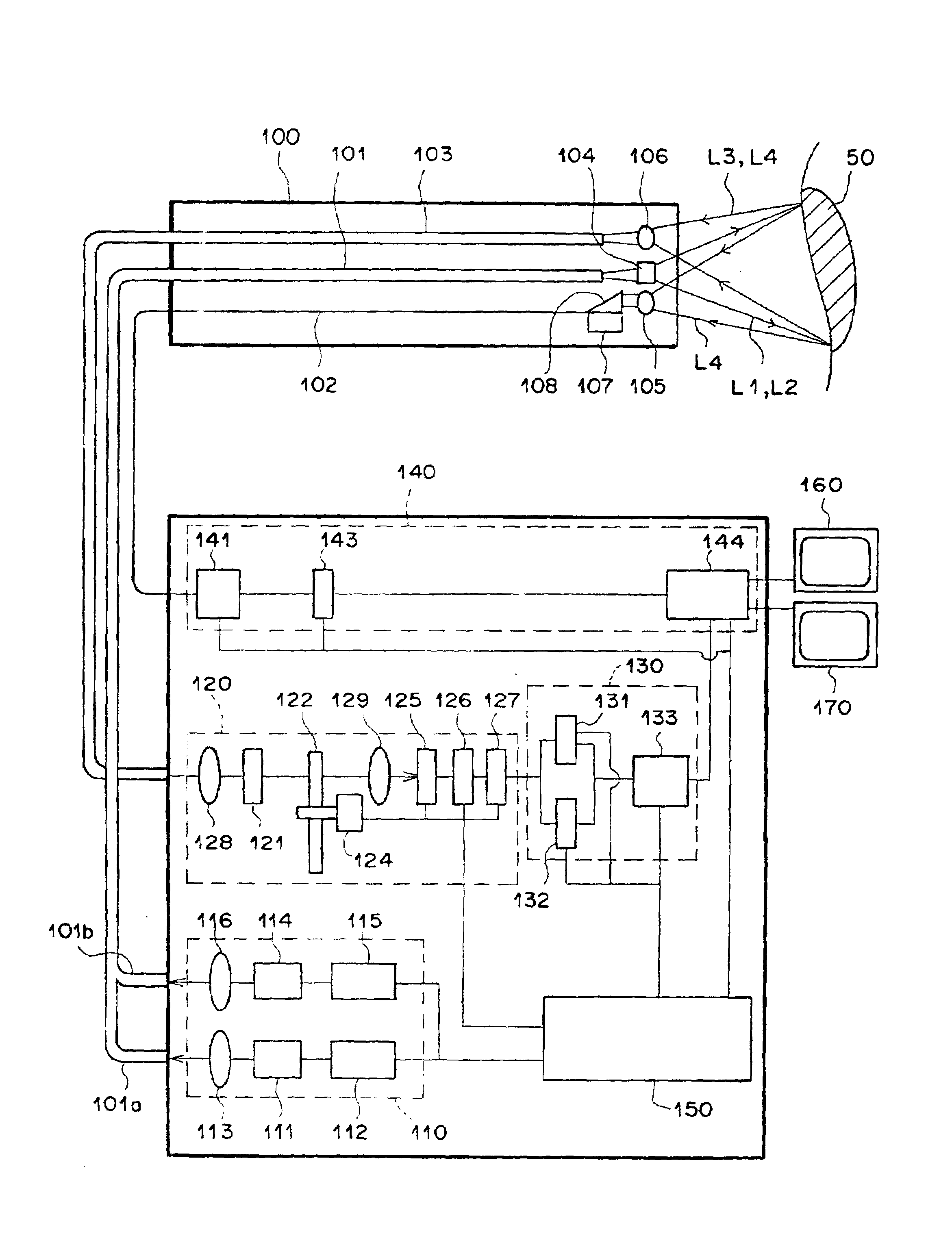
[0108]Hereinafter, with reference to the drawings, the preferred embodiments of the present invention will be explained. First, with reference to FIGS. 4 and 5, a fluorescent endoscope apparatus implementing a fluorescent-light image display apparatus implementing the fluorescent-light image display method according to the present invention will be explained. FIG. 4 is a schematic drawing of a fluorescent endoscope apparatus implementing a fluorescent-light image display apparatus according to the present invention. According to the fluorescent-light image display apparatus of the current embodiment: the fluorescent light emitted from a living-tissue subject is two-dimensionally detected by an image fiber; a narrow-band fluorescent-light image having a wavelength band of 430-530 nm and a wide-band fluorescent-light image having a wavelength band of 430 -730 nm are obtained; a computed-image based on the division value between the pixel values of both images is formed; a hue signal H...

second embodiment

[0142]The fluorescent endoscope apparatus comprises an endoscope insertion portion 100 to be inserted into the body of a patient near the position at which the primary nidus of a disease and areas of suspected secondary infection are located, an illuminating unit for emitting normal-image and IR reflected-light image obtaining-use white-light and fluorescent-light image obtaining-use stimulating-light, a image obtaining unit 300 for obtaining two types of fluorescent-light images having different wavelength bands and a reflected-light image, a composite-image forming unit 400 for computing a division value between the fluorescent-light images, assigning a hue to a computed-image based on the division value and forming a tissue-state image, assigning a luminosity V to the pixel values of an IR reflected-light image and forming a tissue-state image, and combining each of said two tissue-state images to form a composite-image, an image processing unit 500 for performing the image proc...

fourth embodiment

[0163]The fluorescent endoscope apparatus comprises: an endoscope insertion portion 350, provided with a CCD photographing element 156 at the forward end thereof, to be inserted into the body of a patient where the primary nidus and suspected areas of secondary infection are located; an illuminating unit 310 for emitting area-order light (red light Lr, green light Lg, blue light Lb), which is normal-image obtaining-use illuminating light, stimulating-light L2, which is fluorescent-light image obtaining-use stimulating-light, and reference light L5, which is IR reflected-light image obtaining-use reference light; a composite-image forming unit 330 for computing a division value between said fluorescent-light images, assigning a chromaticity (hue and saturation) to a computed-image based on said division value and forming a tissue-state image, for assigning a brightness Z to the pixel values of the IR reflected-light image and forming a tissue-form image, and for combining the tissue...


PUM


Abstract

An image containing data relating to the tissue-state and the tissue-form of a target area is displayed. A fluorescent-light image having two different wavelength bands of fluorescent-light is obtained, based on the strength of the fluorescent light emitted from a target area irradiated by stimulating-light. A reflected-light image is obtained based on the strength of the light reflected from a target area irradiated by white-light as reference-light. A hue is assigned to a computed-image based on a division value of each pixel value of aforementioned fluorescent-light image to form a tissue-state image reflecting mainly the tissue-state, and a brightness is assigned to the reflected-light image to form a tissue-form image reflecting mainly the tissue-form. The tissue-state image and the tissue-form image are combined to form a composite-image, and the composite-image is displayed.

Description

BACKGROUND OF THE INVENTION[0001]1. Field of the Invention[0002]The present invention relates generally to a fluorescent-light image display method and apparatus therefor, and more particularly to a method of and apparatus for detecting the fluorescent-light emitted from a living-tissue subject upon irradiation thereof by a stimulating-light and displaying the detected fluorescent light as an image representing the data relating to the living-tissue subject.[0003]2. Description of the Related Art[0004]It has been known in the field of radiology that when a living-tissue subject is irradiated by a stimulating wavelength having a predetermined wavelength, the strength of the fluorescent light emitted from the normal tissue and the strength of the fluorescent light emitted from the diseased tissue differ. Technologies have been proposed, wherein, by making use of this difference, a living-tissue subject is irradiated by a stimulating-light of a predetermined wavelength and by receiving...

Claims


Application Information

Patent Timeline
Patent Type & Authority Patents(United States)
IPC IPC(8): A61B5/00
CPCA61B5/0071A61B5/0086A61B5/0084
Inventor SENDAI, TOMONARI
Owner FUJIFILM CORP
Why Eureka
Try Eureka