Method and apparatus for separating emulsified water from hydrocarbons
- Summary
- Abstract
- Description
- Claims
- Application Information
AI Technical Summary
Benefits of technology
Problems solved by technology
Method used
Image

Examples
embodiment
Description—Alternate Embodiment
[0129]It is envisioned in an alternate embodiment that the present invention could be utilized for cleaning oils by removal of water therefrom. Such oils could include, for exemplary purposes only, hydraulic oil, turbine oil, lubrication oil, food grade oil and fuel oil.
Operation—Alternate Embodiment
[0130]In this alternate embodiment, oils contaminated by water and containing surfactacts that preclude their ready separation could be readily cleaned through the utilization of the present invention.
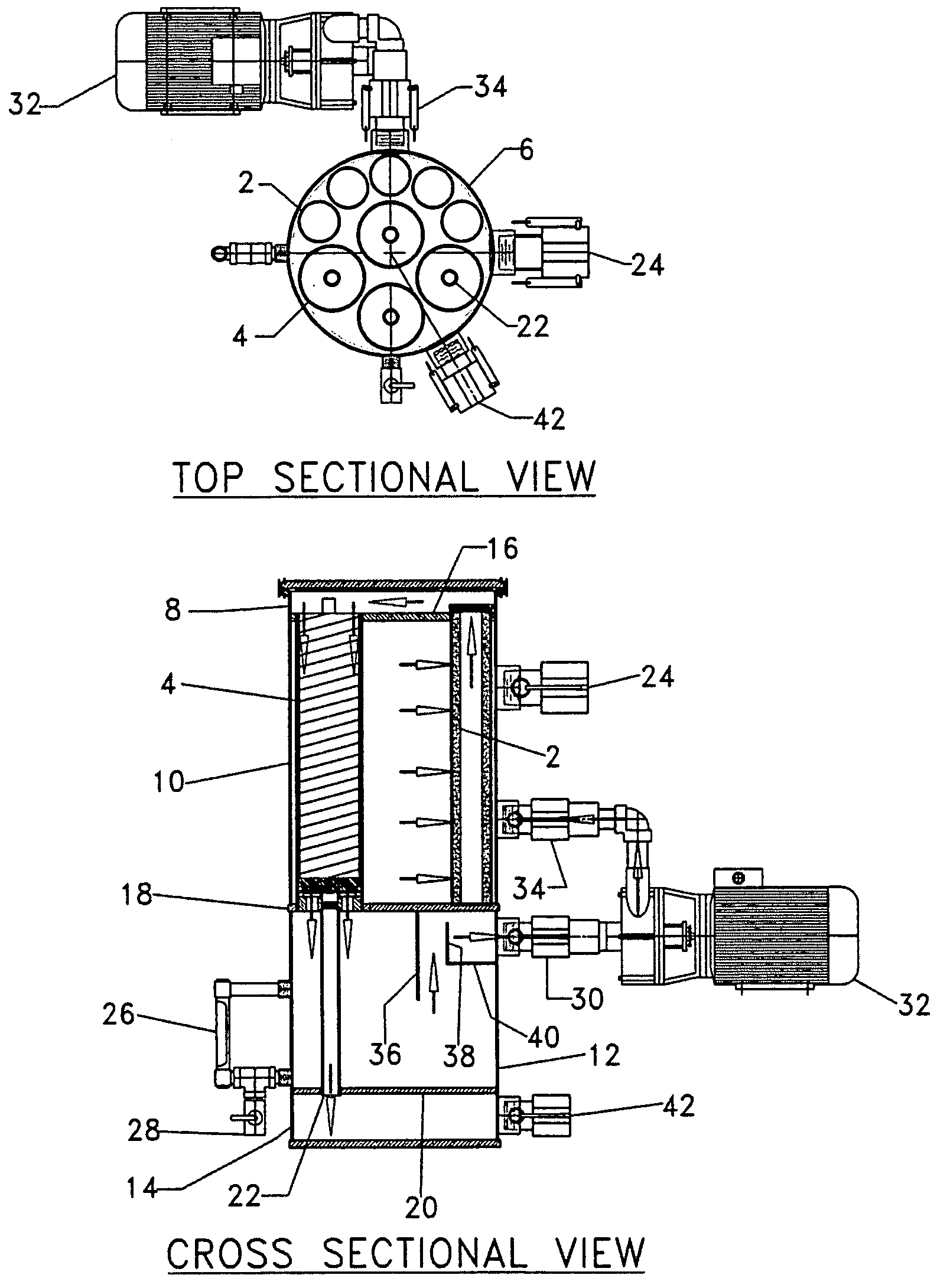
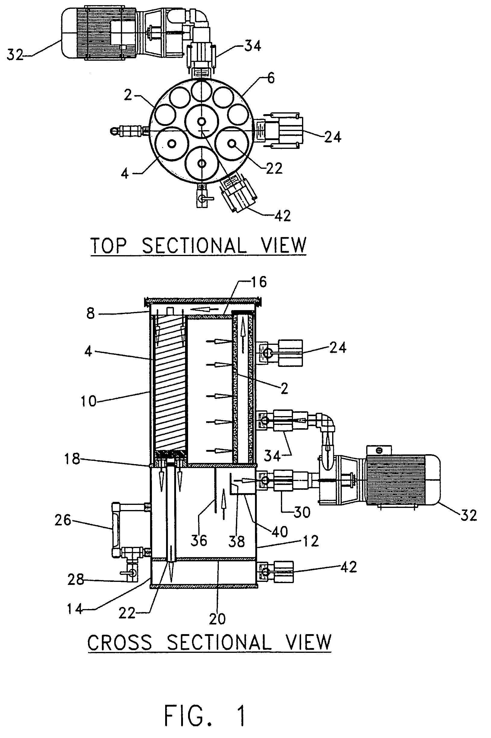
[0131]The present invention utilizes a novel concept of employing a hydrophobic first filter to capture and agglomerate water molecules that are bound into an emulsion through the action of the functional group properties of a surfactant. Prior art has used hydrophilic first filters to capture free water, but these will not function to agglomerate water when the water is emulsified into very small particles that are coated with surfactant.
PUM
| Property | Measurement | Unit |
|---|---|---|
| Temperature | aaaaa | aaaaa |
| Length | aaaaa | aaaaa |
| Fraction | aaaaa | aaaaa |
Abstract
Description
Claims
Application Information
 - Generate Ideas
- Intellectual Property
- Life Sciences
- Materials
- Tech Scout
- Unparalleled Data Quality
- Higher Quality Content
- 60% Fewer Hallucinations
Browse by: Latest US Patents, China's latest patents, Technical Efficacy Thesaurus, Application Domain, Technology Topic, Popular Technical Reports.
© 2025 PatSnap. All rights reserved.Legal|Privacy policy|Modern Slavery Act Transparency Statement|Sitemap|About US| Contact US: help@patsnap.com