GaN-based III-V group compound semiconductor device and p-type electrode for the same

a compound semiconductor and gan-based technology, applied in semiconductor lasers, semiconductor/solid-state device details, lasers, etc., can solve the problem of not having a sufficiently low specific contact resistance of ohmic contact materials, and achieve excellent electrical, optical, and thermal characteristics.

Active Publication Date: 2007-10-23
SAMSUNG ELECTRONICS CO LTD +1
View PDF15 Cites 28 Cited by
  • Summary
  • Abstract
  • Description
  • Claims
  • Application Information

AI Technical Summary

Benefits of technology

[0007]The present invention provides an ohmic contact metal system, which has excellent electrical, optical, and thermal characteristics with respect to a GaN-based semiconductor layer.
[0008]More specifically, to apply GaN-based semiconductor to optical devices, embodiments of the present invention provide an ohmic contact metal system of an electrode formed of a transparent thin layer having good electrical, optical, and thermal characteristics, which are requisite for the manufacturing of a metal electrode using p-type GaN-based semiconductor.
[0017]In the present invention, a p-type electrode, which is formed by depositing a Zn-based alloy or a Zn-based solid solution, is formed of a metal material, which has an excellent oxidation activity to reduce a native oxide layer and functions as a p-type dopant in the p-type semiconductor layer to increase effective hole concentration near the surface of the p-type semiconductor layer. Also, since ZnO obtained by annealing in an air or O2 atmosphere and oxide of a solute added to a Zn-based electrode material have almost the same work function as that of GaN, when they contact p-type GaN, a Schottky barrier height (HBT) can be reduced to improve an ohmic contact characteristic.
[0018]The uppermost electrode layer of the semiconductor device, such as an LD or an LED, should be formed of Au or Ag, which prevents surface degradation during a high-temperature (about 300 to 600° C.) semiconductor manufacturing process, resists oxidation, and has a good wire bonding characteristic and a high transparency.

Problems solved by technology

However, since the Ni / Au thin layer is not appropriate for an LD that requires a lower ohmic contact resistance, a new ohmic contact material having a sufficiently low specific contact resistance is needed.

Method used


Image

  • GaN-based III-V group compound semiconductor device and p-type electrode for the same
  • GaN-based III-V group compound semiconductor device and p-type electrode for the same
  • GaN-based III-V group compound semiconductor device and p-type electrode for the same

Examples


embodiment 1

[0058]In operation 1, at the outset, the surface of a sample, in which a GaN-based semiconductor crystalline layer including a p-type semiconductor layer is formed on a substrate, is washed in an ultrasonic bath at a temperature of 60° C. using trichloroethylene (TCE), acetone, methanol, and distilled water, respectively, for 5 minutes each time. Then, the resultant structure is hard baked at a temperature of 100° C. for 10 minutes to remove the remaining moisture from this sample.

[0059]In operation 2, a photoresist layer is spin-coated on the p-type compound semiconductor layer at 4,500 RPM, and the resultant structure is soft baked at a temperature of 85° C. for 15 minutes.

[0060]In operation 3, to develop a mask pattern, the sample is aligned with a mask, exposed to ultraviolet rays (UV) of 22.8 mW, and dipped in a solution containing a mixture of a developing solution with distilled water in a ratio of 1:4 for 25 seconds.

[0061]In operation 4, the developed sample is dipped in a b...

embodiment 2

[0064]In operation 1′, operations 1 through 4 of the first embodiment are performed in the same manner.

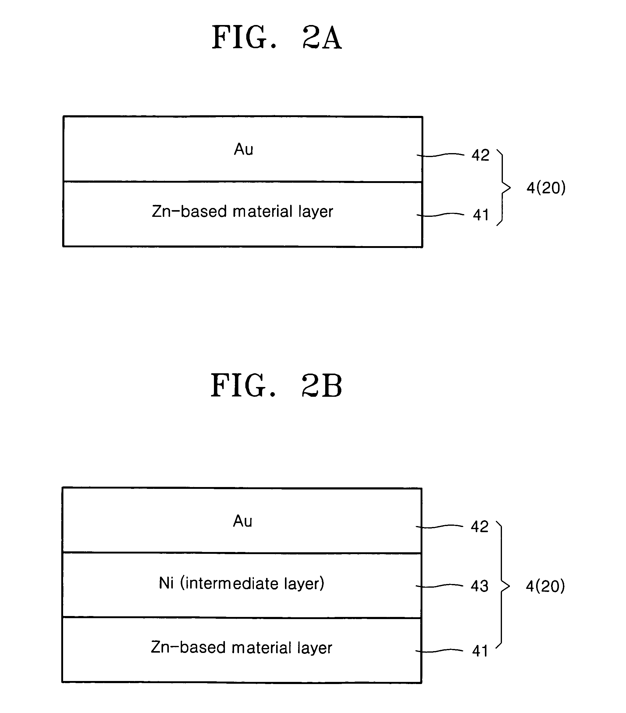
[0065]In operation 2′, a Zn—Ni alloy (10 nm) / Au (10 nm) according to the present invention is deposited on the entire surface of the resultant structure using an e-beam evaporator, and lift-off is carried out using acetone to pattern an electrode.

[0066]In operation 3′, the sample is loaded into an RTA furnace and annealed in an air atmosphere at a temperature of about 350 to 550° C. for 1 minute. As a result, a transparent electrode is formed on the surface of the p-type semiconductor layer disposed on the substrate.

embodiment 3

[0067]In operation 1″, operations 1 through 4 of the first embodiment are performed in the same manner.

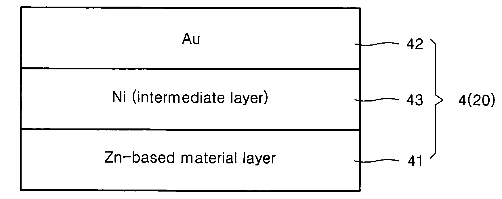
[0068]In operation 2″, a Zn—Ni alloy (3 nm) / Ni (2 nm) / Au (5 nm) according to the present invention is deposited on the entire surface of the resultant structure using an e-beam evaporator, and lift-off is carried out using acetone to pattern an electrode.

[0069]In operation 3″, the sample is loaded into an RTA furnace and annealed in an air atmosphere at a temperature of about 350 to 550° C. for 1 minute. As a result, a transparent electrode is formed on the surface of the p-type semiconductor layer disposed on the substrate.

[0070]As described above, the present invention provides an ohmic electrode forming process, which is one of the most important techniques that enhance commercial availability of LEDs and LDs using p-type GaN-based semiconductor. Thus, GaN-based semiconductor becomes highly commercially available. Also, since the surface of an electrode is in a very good conditi...


PUM

PropertyMeasurementUnit
thicknessaaaaaaaaaa
temperatureaaaaaaaaaa

Abstract

Provided are a p-type electrode and a III-V group GaN-based compound semiconductor device using the same. The electrode includes a first layer disposed on a III-V group nitride compound semiconductor layer and formed of a Zn-based material containing a solute; and a second layer stacked on the first layer and formed of at least one selected from the group consisting of Au, Co, Pd, Pt, Ru, Rh, Ir, Ta, Cr, Mn, Mo, Tc, W, Re, Fe, Sc, Ti, Sn, Ge, Sb, Al, ITO, and ZnO. The Zn-based p-type electrode has excellent electrical, optical, and thermal properties.

Description

[0001]This application claims the priority of Korean Patent Application No. 2003-75219, filed on Oct. 27, 2003, in the Korean Intellectual Property Office, the disclosure of which is incorporated herein in its entirety by reference.BACKGROUND OF THE INVENTION[0002]1. Field of the Invention[0003]The present invention relates to a GaN-based III-V group compound semiconductor device and a p-type electrode for the same.[0004]2. Description of the Related Art[0005]To embody an optical device, such as a light emitting diode (LED) or a laser diode (LD), using GaN-based compound semiconductor, it is very important to form a high-quality ohmic contact between a semiconductor layer and an electrode. An ohmic contact layer for a p-type GaN semiconductor layer may be a Ni-based metal thin layer, i.e., a transparent metal thin layer formed of Ni and Au (refer to U.S. Pat. Nos. 5,877,558 and 6,008,539).[0006]As is known, when a Ni-based thin layer is annealed in an O2 atmosphere, an ohmic contact...

Claims


Application Information

Patent Timeline
Patent Type & Authority Patents(United States)
IPC IPC(8): H01L29/45H01L33/00H01L21/285H01L29/20H01L33/32H01L33/42H01S5/042H01S5/323
CPCH01L21/28575H01L33/40H01L29/452H01L29/2003H01L33/32
Inventor KWAK, JOON-SEOPSEONG, TAE-YEONNAM, OK-HYUNSONG, JUNE-OLEEM, DONG-SEOK
Owner SAMSUNG ELECTRONICS CO LTD
Why Eureka
Try Eureka